Method and Apparatus for Tracking a Rotating Blade Tip for Blade Vibration Monitor Measurements

a technology of vibration monitor and rotating blade, which is applied in the direction of specific gravity measurement, static/dynamic balance measurement, instruments, etc., can solve the problems of weak reflected signal provided by the probe, failure of small gas turbine compressor blade, and limited measurement provided by the line prob

Inactive Publication Date: 2009-03-26
SIEMENS ENERGY INC
View PDF12 Cites 39 Cited by
  • Summary
  • Abstract
  • Description
  • Claims
  • Application Information

AI Technical Summary

Problems solved by technology

Due to their complex design, natural resonant mechanical frequencies of the blades may coincide with or be excited by certain blade rotational speeds and rotational harmonics thereof.
Further, there is a current interest in obtaining measurement of high frequency vibration modes that result in failures of small gas turbine compressor blades, unlike lower vibration modes that result in movement of the blade as a whole, these high frequency modes form closely spaced nodes and antinodes across the compressor blades.
In addition, the measurements provided by these line probes are limited to the vibration occurring at the leading or trailing edge, and the reflected signals provided by these probes are weak since the laser light must be distributed over a line, rather than being provided to a single small point on the blade tip edge.
Current vibration measurement techniques generally do not provide accurate information as to the exact position along the blade tip of the vibration measurements.
Further, this unknown position of the vibration measurements changes as the rotor moves axially with respect to the case mounted sensor due to spins up and down, as the turbine warms up and cools down, and as the load on the turbine changes.
Hence, it is not possible to accurately predict vibration elsewhere in the blade, or determine the maximum stress developed in the blade.

Method used


Image

  • Method and Apparatus for Tracking a Rotating Blade Tip for Blade Vibration Monitor Measurements
  • Method and Apparatus for Tracking a Rotating Blade Tip for Blade Vibration Monitor Measurements
  • Method and Apparatus for Tracking a Rotating Blade Tip for Blade Vibration Monitor Measurements

Examples


Embodiment Construction

[0017]In the following detailed description of the preferred embodiment, reference is made to the accompanying drawings that form a part hereof, and in which is shown by way of illustration, and not by way of limitation, specific preferred embodiments in which the invention may be practiced. It is to be understood that other embodiments may be utilized and that changes may be made without departing from the spirit and scope of the present invention.

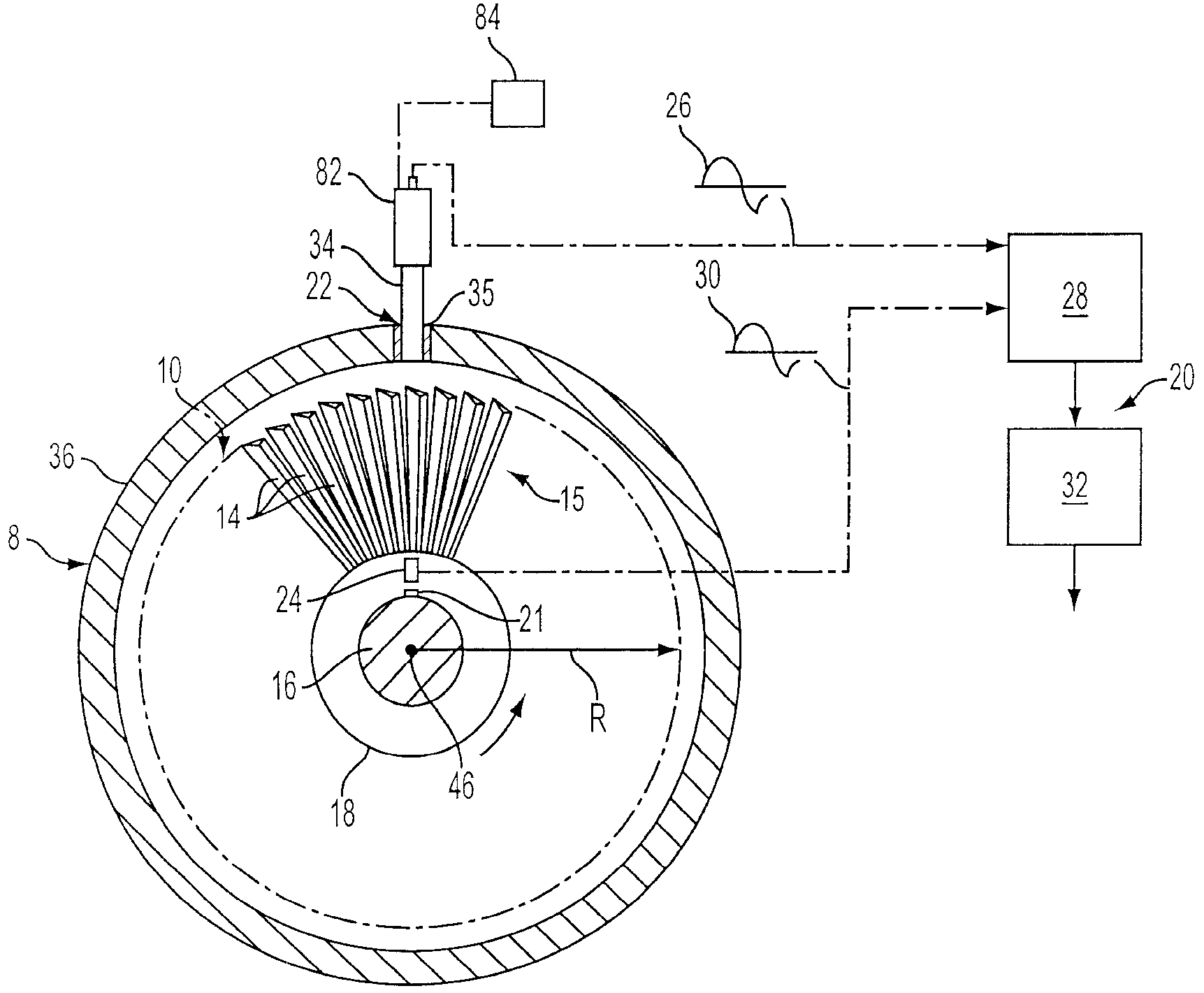
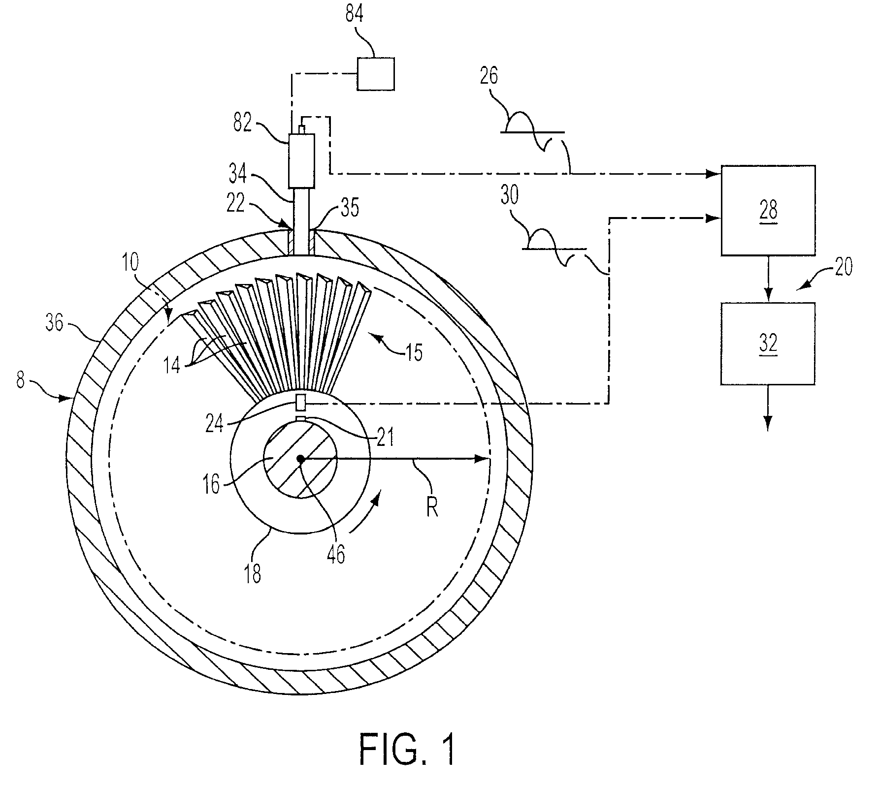
[0018]FIG. 1 diagrammatically illustrates a turbine 8 including an unshrouded compressor blade row 10 in which the method and apparatus of the present invention can be employed in a blade vibration monitoring system to monitor nonsynchronous compressor blade vibrations. Turbine blades 14 are connected to a rotor 16 by means of a rotor disk 18 and form a blade structure 15 within the turbine 8.

[0019]A nonsynchronous turbine blade vibration monitoring system (BVM) 20 is also shown in FIG. 1. The system 20 includes a turbine blade probe stru...


PUM


Abstract

A method and apparatus for monitoring vibrations in a blade structure of a turbine including generating signals from a probe located adjacent to a radial outer edge of the blade structure to provide signals corresponding to vibrations at predetermined locations along the tips of the blades. A leading edge of a blade tip is detected during a blade tracking operation, and a known location along the length of the blade tips is monitored during a vibration measurement operation. The measurement operation may be performed simultaneously with the tracking operation to provide measurements as the axial location of the blades change during transitional modes of operation of the turbine.

Description

FIELD OF THE INVENTION[0001]The present invention relates to a method of monitoring a blade structure in a turbine and, more particularly, to a method of tracking the location of a blade tip to provide time-of-arrival measurements from a known location on the blade tip for use in a blade vibration monitoring system.BACKGROUND OF THE INVENTION[0002]A high speed turbo machine, such as, for example, a steam or gas turbine, generally comprises a plurality of blades arranged in axially oriented rows, the rows of blades being rotated in response to the force of a high pressure fluid flowing axially through the machine. Due to their complex design, natural resonant mechanical frequencies of the blades may coincide with or be excited by certain blade rotational speeds and rotational harmonics thereof. To prevent excessive vibration of the blade about its normal position, prudent design practice dictates that the blades be constructed such that the frequencies of the lowest modes fall betwee...

Claims


Application Information

Patent Timeline
Patent Type & Authority Applications(United States)
IPC IPC(8): G01H11/00
CPCG01H1/006
Inventor TWERDOCHLIB, MICHAEL
Owner SIEMENS ENERGY INC
Why Eureka
Try Eureka