Transaxle Provided With Power Take-Off Device

Active Publication Date: 2009-03-26
KANZAKI KOKYUKOKI MFG
View PDF2 Cites 9 Cited by
  • Summary
  • Abstract
  • Description
  • Claims
  • Application Information

AI Technical Summary

Benefits of technology

[0012]Preferably, one or more holes opened on the outer side surface of the power take-off support portion are coincided to one or more holes opened on the inner side surface of the base casing member respectively, and one or more fasteners are passed through the mutually coinciding holes respectively, so as to fasten the base casing member to the power take-off support portion. Such a simple and usual manner is adapted to fix the base casing member to the power take-off support portion so as t

Problems solved by technology

However, such a PTO casing is disadvantageous in minimization of the vehicle and in facilitation of mounting thereof.
Further, the PTO shaft during rotation transmits undesirable vibration to the PTO casing so as to undesirably vibrate the vehicle frame.
However, while the first transaxle can be easily standardized

Method used


Image

  • Transaxle Provided With Power Take-Off Device
  • Transaxle Provided With Power Take-Off Device
  • Transaxle Provided With Power Take-Off Device

Examples


first embodiment

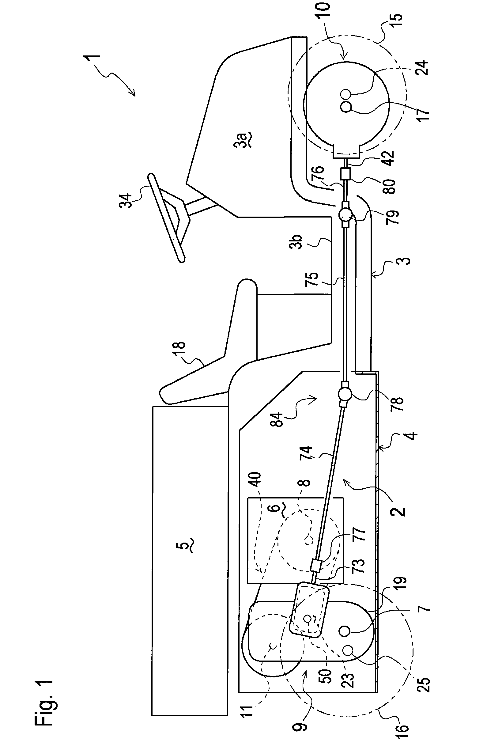
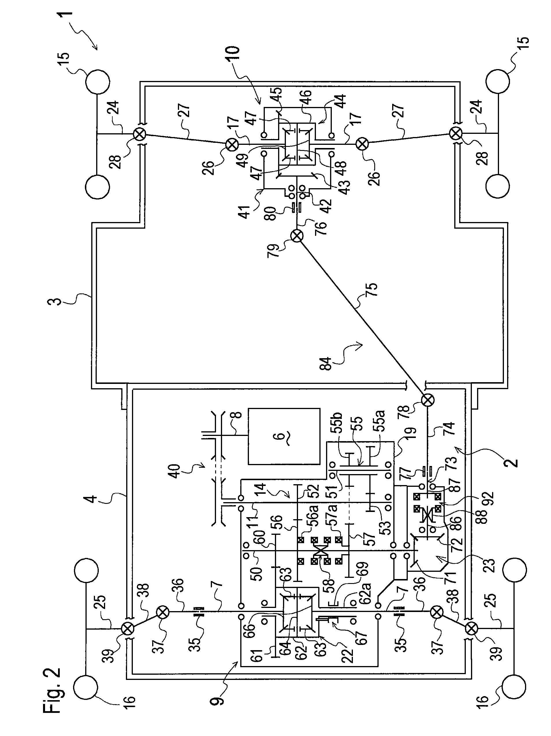
[0057]Four-wheel driving power transmission system 2, including PTO gear transmission mechanism 23 in the PTO casing and including power train 84, will be described with reference to FIGS. 1 to 12.

[0058]As shown in FIGS. 1, 2 and 4, power train 84, interposed between PTO shaft 73 supported by the PTO casing and input shaft 42 of front transaxle 10, includes a first propeller shaft 74, a second propeller shaft 75 and a third propeller shaft 76. First propeller shaft 74 is rotatably integrally connected coaxially to PTO shaft 73 through a coupler 77, and third propeller shaft 76 is rotatably integrally connected coaxially to input shaft 42 through coupler 80 as mentioned above. First and second propeller shafts 74 and 75 are connected to each other through a universal joint 78. Second and third propeller shafts 75 and 76 are connected to each other through a universal joint 79.

[0059]PTO shaft 73 supported by the PTO casing is extended in the fore-and-aft direction of vehicle 1 when v...

second embodiment

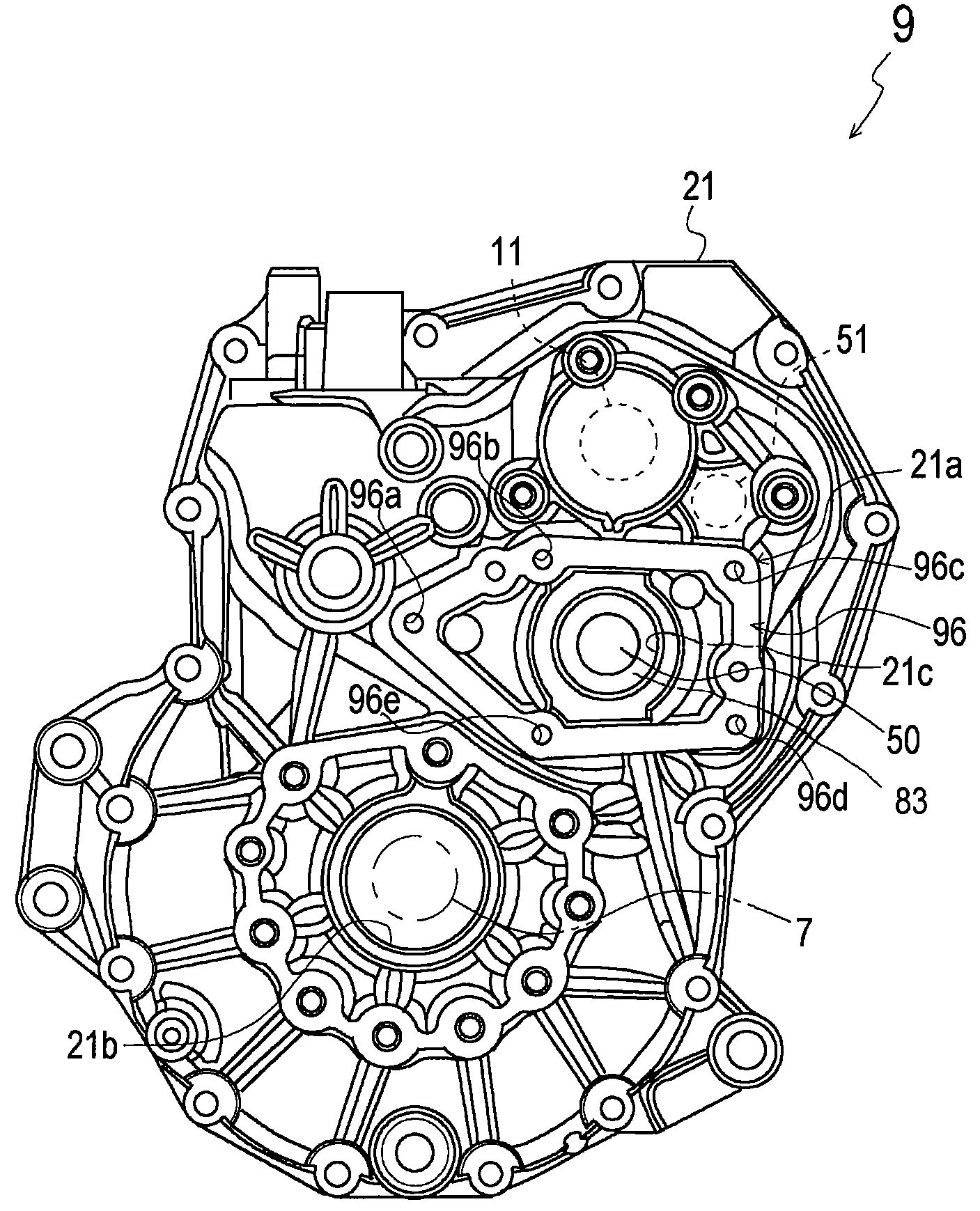
[0081]On the other hand, inner side surface 194 is formed annularly to surround a shaft hole 181a to coincide to shaft hole 21c, and bolt holes 194b, 194c, 194d and 194e are provided in inner side surface 194. Bolt holes 196a in outer side surface 195 are more in number than bolt holes 194b, 194c, 194d and 194e, so that four of all bolt holes 196a are optionally selected to correspond to bolt holes 194b, 194c, 194d and 194e. In this way, in the second embodiment, the projection direction of PTO shaft 73 supported by PTO main casing member 82 relative to PTO support portion 21a is selected depending on which bolt holes 196a are selected to coincide to bolt holes 194b, 194c, 194d and 194e, so as to pass bolts 98 therethrough. The selection of bolt holes 196a to coincide to bolt holes 194b, 194c, 194d and 194e depends on change of the rotational position of base casing member 181 centered on the axis of counter shaft 50.

[0082]Therefore, in the second embodiment, only standardized base ...

third embodiment

[0084]On the other hand, inner side surface 294 is formed annularly to surround a shaft hole 281a to coincide to shaft hole 21c, and four bolt slots 294b, 294c, 294d and 294e are provided in inner side surface 294. Bolt slots 294b, 294c, 294d and 294e are elongated in the circular direction centered on the axis of counter shaft 50. In the third embodiment, inner side surface 294 of base casing member 281 is fitted to outer side surface 296 of PTO support portion 21a, and bolt hole 294b coincides to bolt hole 296b, bolt hole 294c to bolt hole 296c, bolt hole 294d to bolt hole 296d, and bolt hole 294e to bolt hole 296e, respectively, so as to pass bolts 98 therethrough. The projection direction of PTO shaft 73 supported by PTO main casing member 82 relative to PTO support portion 21a can be changed by changing the rotational position of base casing member 281 relative to outer side surface 296 of PTO support portion 21a so as to change the positions in respective bolt slots 294b, 294c...


PUM


Abstract

A power take-off support portion, including a shaft hole and an outer side surface formed around the shaft hole, is formed on a transaxle housing. The outer side surface of the power take-off support portion is shaped to fit a power take-off casing supporting a power take-off shaft in a first direction. A power take-off casing includes a power take-off main casing member and a base casing member joined to each other. The base casing member is formed with an inner side surface and an outer side surface. The inner side surface and the outer side surface of the base casing member are shaped so that the power take-off shaft supported by the power take-off main casing member is oriented in a second direction different from the first direction when the inner side surface of the base casing member is fitted to the outer side surface of the power take-off support portion, and the outer side surface of the base casing member is fitted to the inner side surface of the power take-off main casing member.

Description

BACKGROUND OF THE INVENTION[0001]1. Field of the Invention[0002]The present invention relates to a transaxle provided with a power take-off (hereinafter, “PTO”) device for transmitting power from a transmission in the transaxle. In one embodiment, the transaxle is available to a four-wheel driving vehicle such as a utility vehicle, and the power take-off device is adapted for transmitting power to another transaxle.[0003]2. Related Art[0004]As disclosed in Japanese Laid-Open Gazette No. 2005-297673, there exists a well-known and conventional four-wheel drive vehicle. In the vehicle, a first transaxle is provided for driving two wheels at either the front or rear portion of the vehicle, and a second transaxle is provided for driving two wheels at the other portion of the vehicle. The first transaxle is provided with an input portion on one of right and left sides thereof, and is provided with a PTO shaft on the other of right and left sides thereof laterally opposite to the input por...

Claims


Application Information

Patent Timeline
IPC IPC(8): F16H57/02B60K17/00B60K17/344
CPCY10T74/2186B60K17/34
Inventor NISHIMOTO, SHUJI
Owner KANZAKI KOKYUKOKI MFG
Why Eureka
Try Eureka