Guide Plate of Chain Saw

a chain saw and guide plate technology, applied in the direction of chain saws, metal working devices, manufacturing tools, etc., can solve the problems of hardly cutting to form figures and high cost of steady material, and achieve the effect of no material waste and cost reduction

Inactive Publication Date: 2009-03-26
CHANG LI SHUA +2
View PDF7 Cites 0 Cited by
  • Summary
  • Abstract
  • Description
  • Claims
  • Application Information

AI Technical Summary

Benefits of technology

[0011]Compared to prior arts, the present invention adopts the way of welding the welded welding powder structures with steadite material at the front end of the guide plate so as to easily form a figure what is requested, and having no material wasted. It is then that the cost is down. On the other hand, the newly formed guide plate is more accurate and safer, so that the jammed chain will not be happening.

Problems solved by technology

A steadite plate is welded on the front end of the guide plate in prior arts, but the steadite material is expensive and hardly cut to form a figure what is requested except laser machining.

Method used


Image

  • Guide Plate of Chain Saw
  • Guide Plate of Chain Saw
  • Guide Plate of Chain Saw

Examples


Embodiment Construction

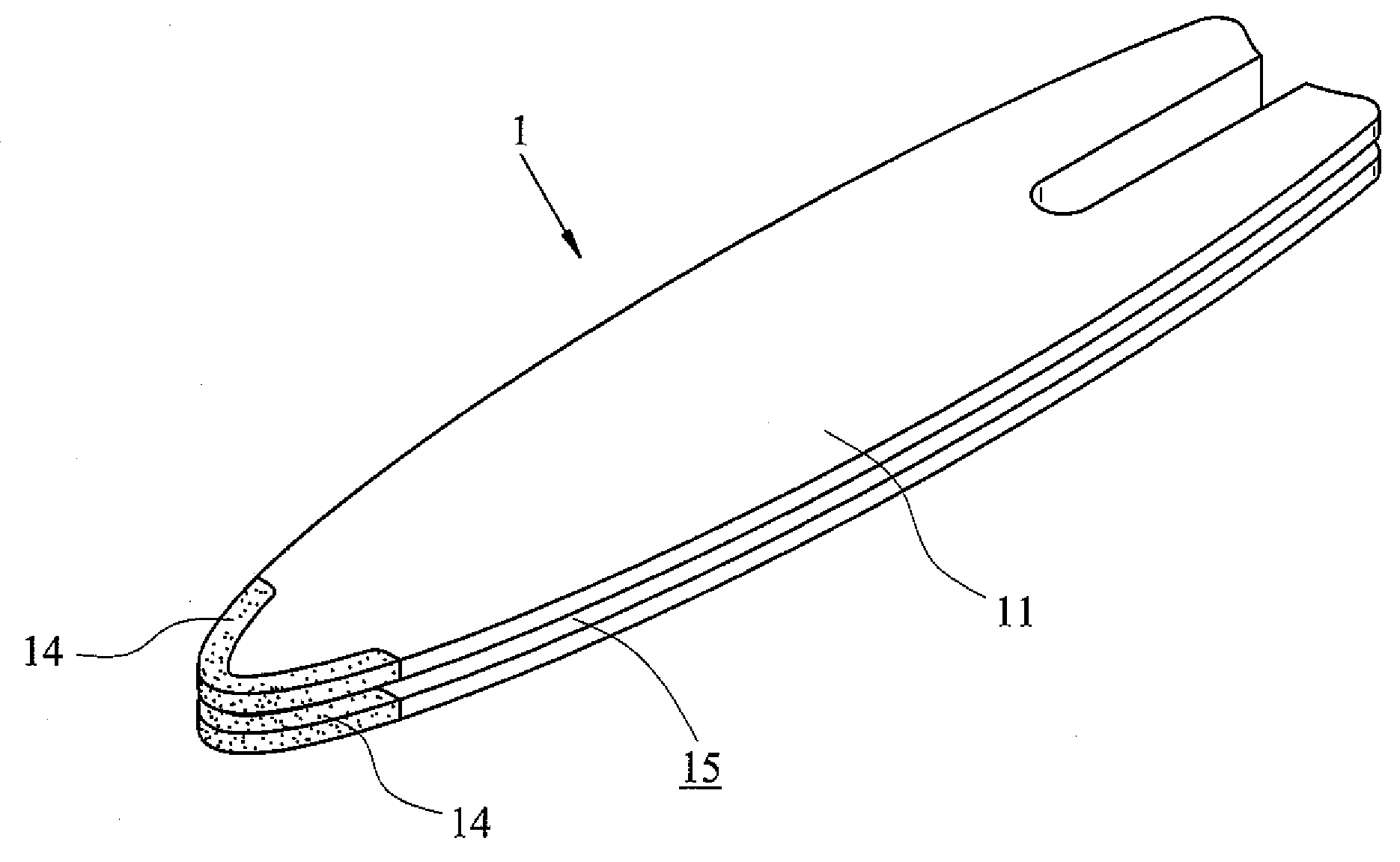
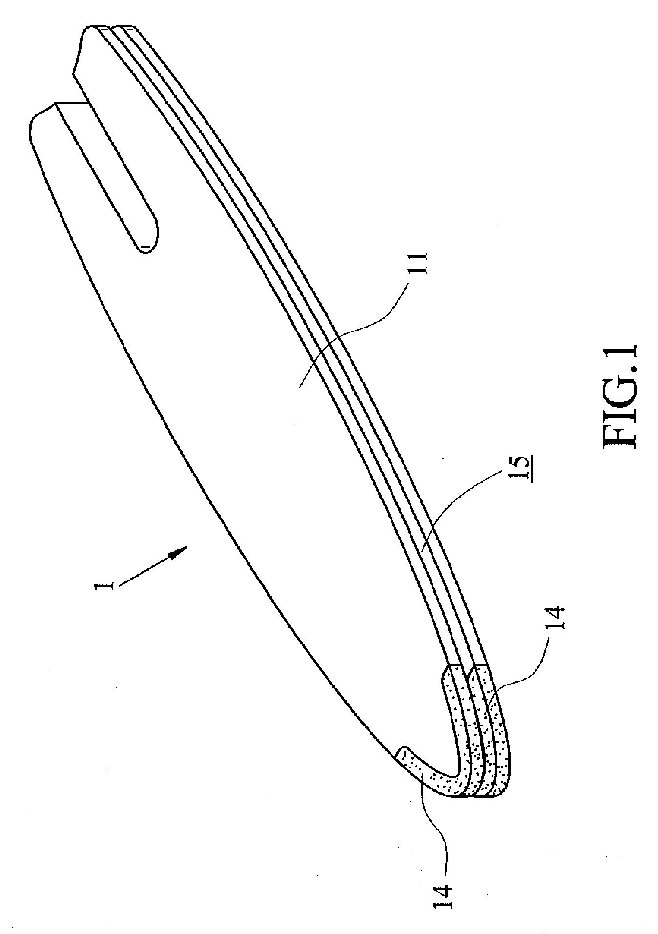
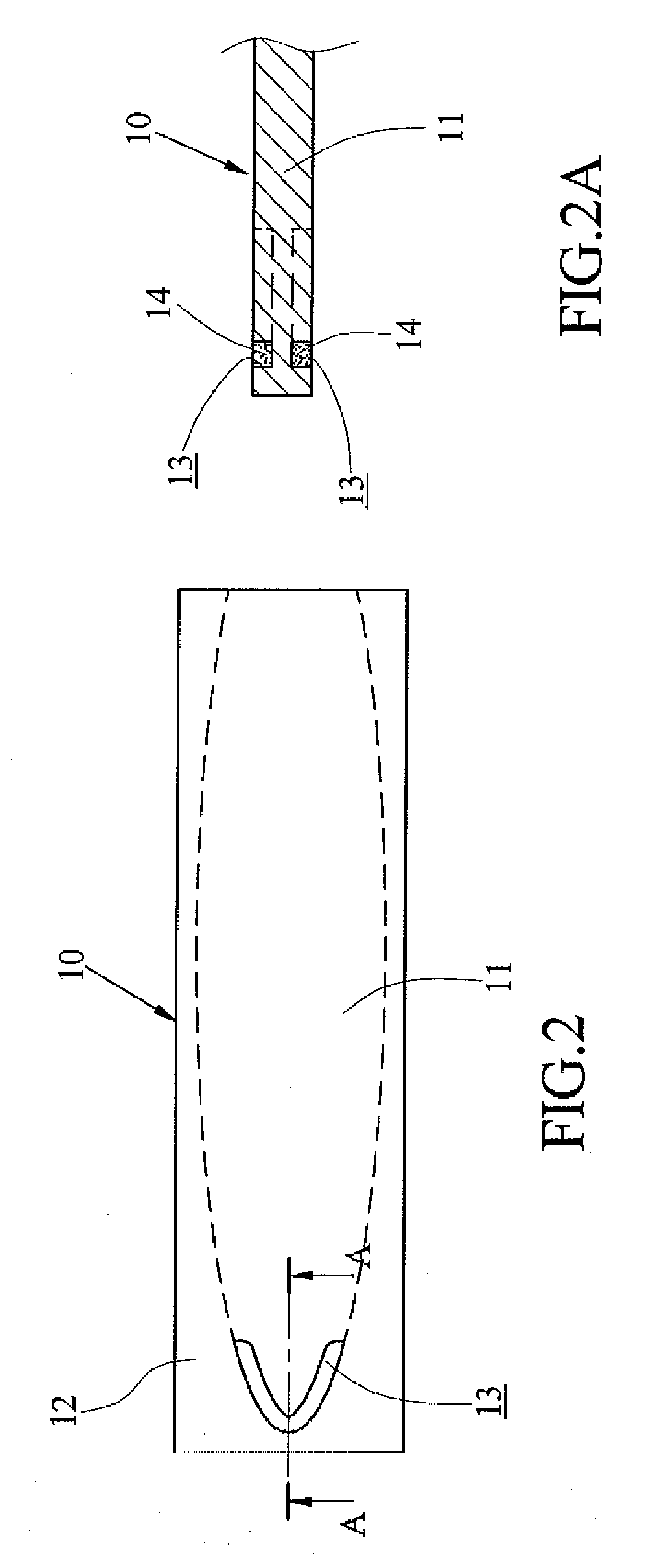
[0021]With reference to FIG. 1 to FIG. 4, which are illustrating a schematic 3-D view of the present invention; a schematic structural view of forming two indentations of the present invention; a schematic sectional view of the two indentations and two welded welding powder structures of the present invention; a schematic structural view of separating an eliminated portion of the present invention; and a schematic structural view of forming a guide groove of the present invention; the guide plate 1 of the chain saw of the present invention includes: a rectangular metal plate 10 in FIG. 2, which is constructed by a body 11 shaped as a guide plate and an eliminated portion 12 elongated around the peripheral of the body 11, as shown in FIG. 2; wherein the two surfaces of the front end of the body 11 are elongated to a boundary surface of the eliminated portion 12 individually and corresponding to two indentations 13 of an arc portion toward front, as shown in FIG. 2A, the two indentati...


PUM

PropertyMeasurementUnit
hardnessaaaaaaaaaa
poweraaaaaaaaaa
tenacityaaaaaaaaaa

Abstract

A guide plate of a chain saw is disclosed and the guide plate comprises: a rectangular metal plate, which is constructed by a body shaped as a guide plate and an eliminated portion elongated around the peripheral of the body; wherein the two surfaces of the front end of the body are elongated to a boundary surface of the eliminated portion individually and corresponding to two indentations of an arc portion toward front, two welded welding powder structures are inside the two indentations so as to let the top surface and the bottom surface of the metal plate be two flat surfaces, the body is separated from the eliminated portion, the welded welding powder structures are disposed at the front edge of the front end of the body, a guide groove is disposed in between the two welded welding powder structures and toward the body.

Description

BACKGROUND OF THE INVENTION[0001]1. Field of the Invention[0002]The present invention generally relates to a guide plate of a chain saw, more particularly to a guide plate which is capable of saving materials while in manufacturing.[0003]2. Description of the Prior Art[0004]Chain saw is powered to cut wood, stone, etc. and equipped with a power portion and a guide plate firmly disposed on the power portion. A guide groove is disposed on the peripheral of the guide plate so as to let the chain revolve in safety. Therefore, for safety, the design, material, hardness, and convenience of the guide plate are developed from different views.[0005]With reference to FIG. 5, which illustrates a schematic 3-D view of a chain saw in prior arts A chain saw 30 mainly includes a power portion 31, a chain 32 and a guide plate 33; wherein the power portion 31 is wrapped by a case 34 with a handle 35. The guide plate 33 is to guide the chain 32. Due to that the friction of the guiding plate 33 and th...

Claims


Application Information

Patent Timeline
Patent Type & Authority Applications(United States)
IPC IPC(8): B26D5/00
CPCB27B17/025Y10T83/7264
Inventor CHANG, LI SHUATSAI, EDWARD YEE-HUATSAI, STEPHEN YEE-FONG
Owner CHANG LI SHUA
Why Eureka
Try Eureka