Deposition system for thin film formation

Active Publication Date: 2009-03-26
EASTMAN KODAK CO
View PDF20 Cites 147 Cited by
  • Summary
  • Abstract
  • Description
  • Claims
  • Application Information

AI Technical Summary

Benefits of technology

[0044]It is an advantage of the present invention that it can provide a compact apparatus for atomic layer deposition onto a substrate that is well suited to a number of different types of substrates and deposition environments.
[0045]It is a further advantage of the present invention that it allows operation, in preferred embodiments, under atmospheric pressure conditions.
[0046]It is yet a further advantage of the present invention that it is adaptable for deposition on a web or other moving substrate, including deposition onto a large area substrate.
[0047]It is still a further advantage of the present invention that it can be employed in low temperature processe

Problems solved by technology

In practice, in any system it is difficult to avoid some direct reaction of the different precursors leading to a small amount of chemical vapor deposition reaction.
Self-saturating surface reactions make ALD relatively insensitive to transport non-uniformities, which might otherwise impair surface uniformity, due to engineering tolerances and the limitations of the flow system or related to surface topography (that is, deposition into three dimensional, high aspect ratio structures).
As a general rule, a non-uniform flux of chemicals in a reactive process generally results in different completion times over different portions of the surface area.
However, in spite of its inherent technical capabilities and advantages, a number of technical hurdles still remain.
However, it is difficult to obtain a reliable scheme for introducing the needed series of gaseous formulations into a chamber at the needed speeds and without some unwanted mixing.
In a typical ALD chamber the volume (V) and pressure (P) are dictated independently by the mechanical and pumping constraints, leading to difficulty in precisely controlling the residence time to low values.
Existing ALD approaches have been compromised with the trade-off between the need to shorten reaction times with improved chemical utilization efficiency, and, on the other hand, the need to minimize purge-gas residence and chemical removal times. One approach to overcome the inherent limitations of “pulsed” delivery of gaseous material is to provide each reactant gas continuously and to move the substrate t

Method used


Image

  • Deposition system for thin film formation
  • Deposition system for thin film formation
  • Deposition system for thin film formation

Examples


Embodiment Construction

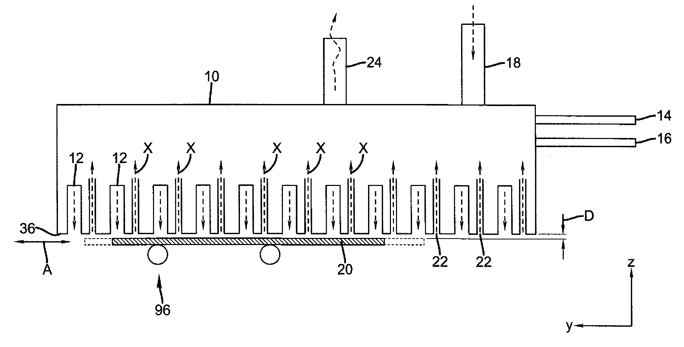
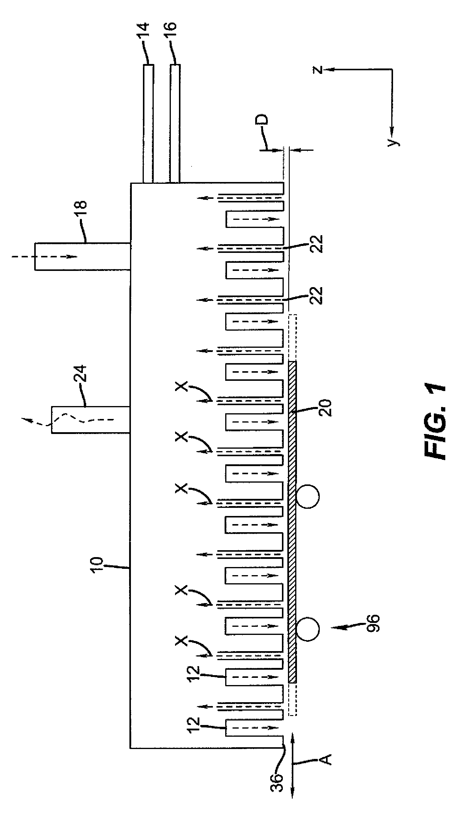
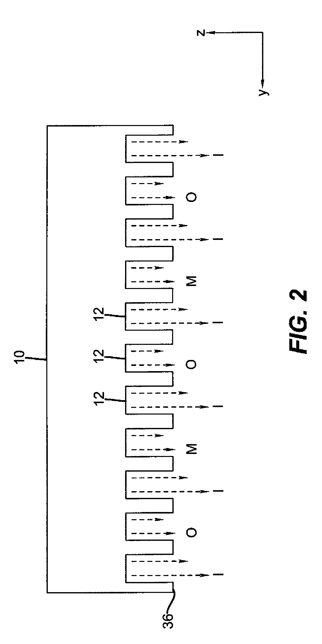
[0091]The present description is directed in particular to elements forming part of, or cooperating more directly with, apparatus in accordance with the invention. It is to be understood that elements not specifically shown or described may take various forms well known to those skilled in the art.

[0092]For the description that follows, the term “gas” or “gaseous material” is used in a broad sense to encompass any of a range of vaporized or gaseous elements, compounds, or materials. Other terms used herein, such as: reactant, precursor, vacuum, and inert gas, for example, all have their conventional meanings as would be well understood by those skilled in the materials deposition art. The figures provided are not drawn to scale but are intended to show overall function and the structural arrangement of some embodiments of the present invention.

[0093]For many thin film applications the substrate is commonly considered as a sheet of material which may or may not be planar. Examples of...


PUM

PropertyMeasurementUnit
Angleaaaaaaaaaa
Lengthaaaaaaaaaa
Weightaaaaaaaaaa

Abstract

An apparatus for maintaining the alignment or positional relationship between at least two coating modules in an ALD system, the apparatus comprising a plurality of coating modules in a coating section, at least a first bar and a second bar for supporting the coating modules, and at least a first bar mounting structure and a second bar mounting structure for supporting the bars, wherein each of the coating modules are supported by the first bar and the second bar, and wherein the combination of the at least two coating modules and the first bar and the second bar define a coating section profile for the output faces of the coating modules. Also disclosed is a process for making such apparatus.

Description

CROSS-REFERENCE TO RELATED APPLICATIONS[0001]The present application is related to U.S. application Ser. No. 11 / 392,007, filed Mar. 29, 2006 by Levy and entitled, “PROCESS FOR ATOMIC LAYER DEPOSITION,” U.S. application Ser. No. 11 / 392,006, filed Mar. 29, 2006 by Levy and entitled “APPARATUS FOR ATOMIC LAYER DEPOSITION,” U.S. application Ser. No. 11 / 620,738, filed Jan. 8, 2007, by Levy and entitled “DELIVERY DEVICE FOR DEPOSITION,” U.S. application Ser. No. 11 / 620,740, filed Jan. 8, 2007 by Nelson et al. and entitled “DELIVERY DEVICE COMPRISING GAS DIFFUSER FOR THIN FILM DEPOSITION,” U.S. Application Ser. No, 11 / 620,744, filed Jan. 8, 2007 by Levy and entitled, “DEPOSITION SYSTEM AND METHOD USING A DELIVERY HEAD SEPARATED FROM A SUBSTRATE BY GAS PRESSURE,” U.S. Application Ser. No. ______ (docket 94079), filed concurrently herewith by Levy et al. and entitled, “SYSTEM FOR THIN FILM DEPOSITION UTILIZING COMPENSATING FORCES,” US Application Ser. No. ______ (docket 94217), filed concurr...

Claims


Application Information

Patent Timeline
IPC IPC(8): C23C16/00
CPCC23C16/45551C23C16/45563C23C16/54H01L21/68C30B35/00H01L21/67173H01L21/6719C30B25/14B33Y80/00
Inventor KERR, ROGER S.LEVY, DAVID H.
Owner EASTMAN KODAK CO
Why Eureka
Try Eureka