Power cord cooling apparatus for a vacuum cleaner

Active Publication Date: 2009-03-26
SAMSUNG GWANGJU ELECTRONICS CO LTD
View PDF1 Cites 7 Cited by
  • Summary
  • Abstract
  • Description
  • Claims
  • Application Information

AI Technical Summary

Benefits of technology

[0007]Accordingly, to solve at least the above problems and / or disadvantages and to provide at least the advantages described below, it is a non-limiting object of the present invention to provide a power cord cooling apparatus for a vacuum cleaner capable of enhancing a cooling efficiency thereof, the power cord cooling apparatus for a vacuum cleaner comprising a power cord cooling apparatus disposed in a cord reel chamber formed inside a main body of the vacuum cleaner to cool a power cord wound around a cord reel, wherein the power cord cooling apparatus allows outside air to enter the cord reel chamber, to contact the power cord wound around the cord reel, and to be discharged outside the cord reel chamber via a center space in the cord reel.

Problems solved by technology

If the vacuum cleaner has high electrical consumption, the power cord of the vacuum cleaner generates more heat.
As the power cord is wound on the cord reel, the power cord cannot emit heat as effectively.
Accordingly, after the vacuum cleaner has been used for a long time, the heat generated by the power cord may cause the temperature of the power cord to rise as the power cord is wound around the cord reel.
If the temperature rises enough, the sheath of the power cord or the plastic cord reel may melt, causing the power cord to stick together or even short circuit.
Heat generated from the power cord therefore cannot be effectively dissipated.

Method used


Image

  • Power cord cooling apparatus for a vacuum cleaner
  • Power cord cooling apparatus for a vacuum cleaner
  • Power cord cooling apparatus for a vacuum cleaner

Examples


Embodiment Construction

[0022]Reference will now be made in detail to the non-limiting embodiments of the present invention by way of reference to the drawings, wherein like reference numerals refer to like parts, components and structures.

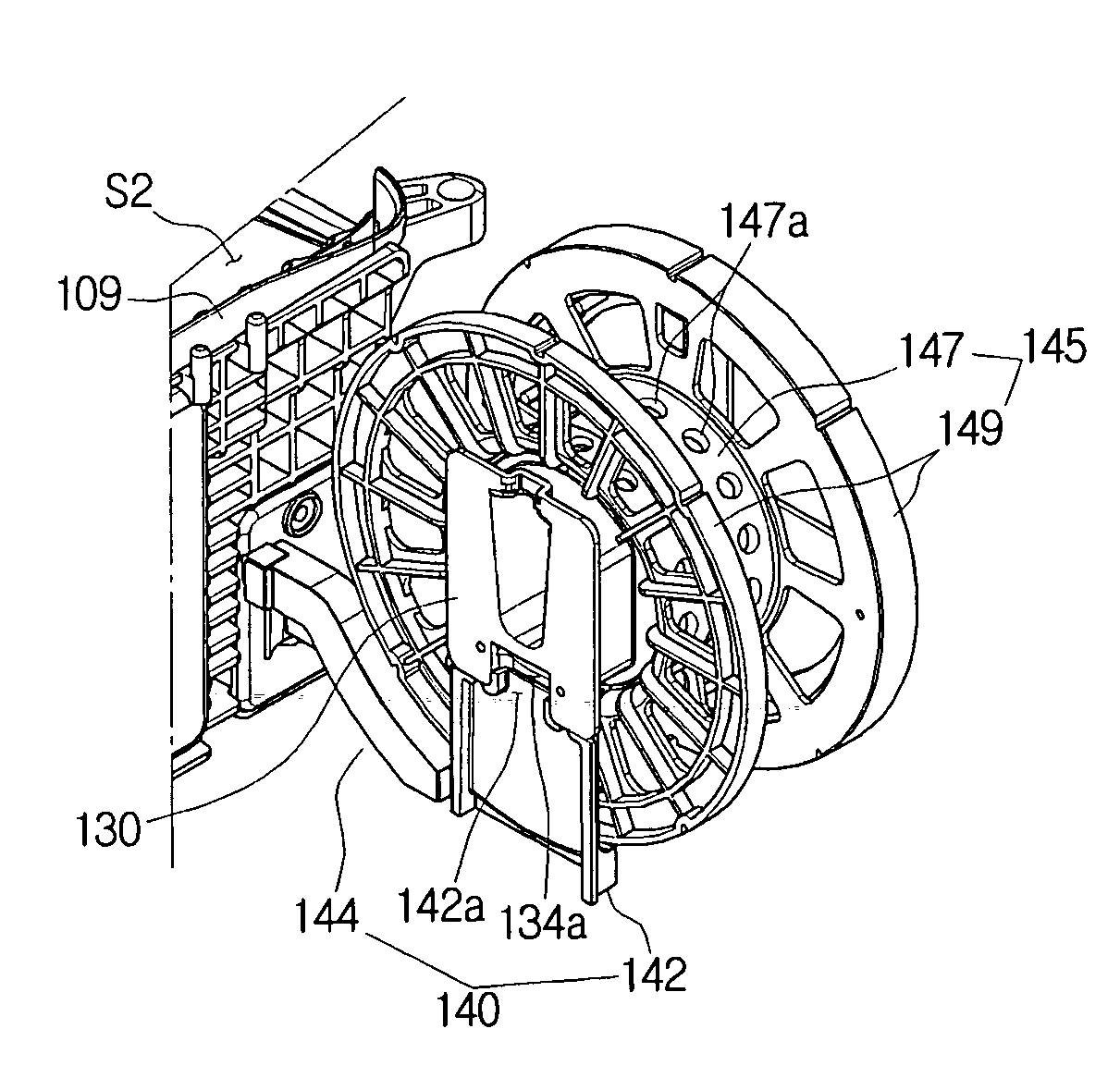
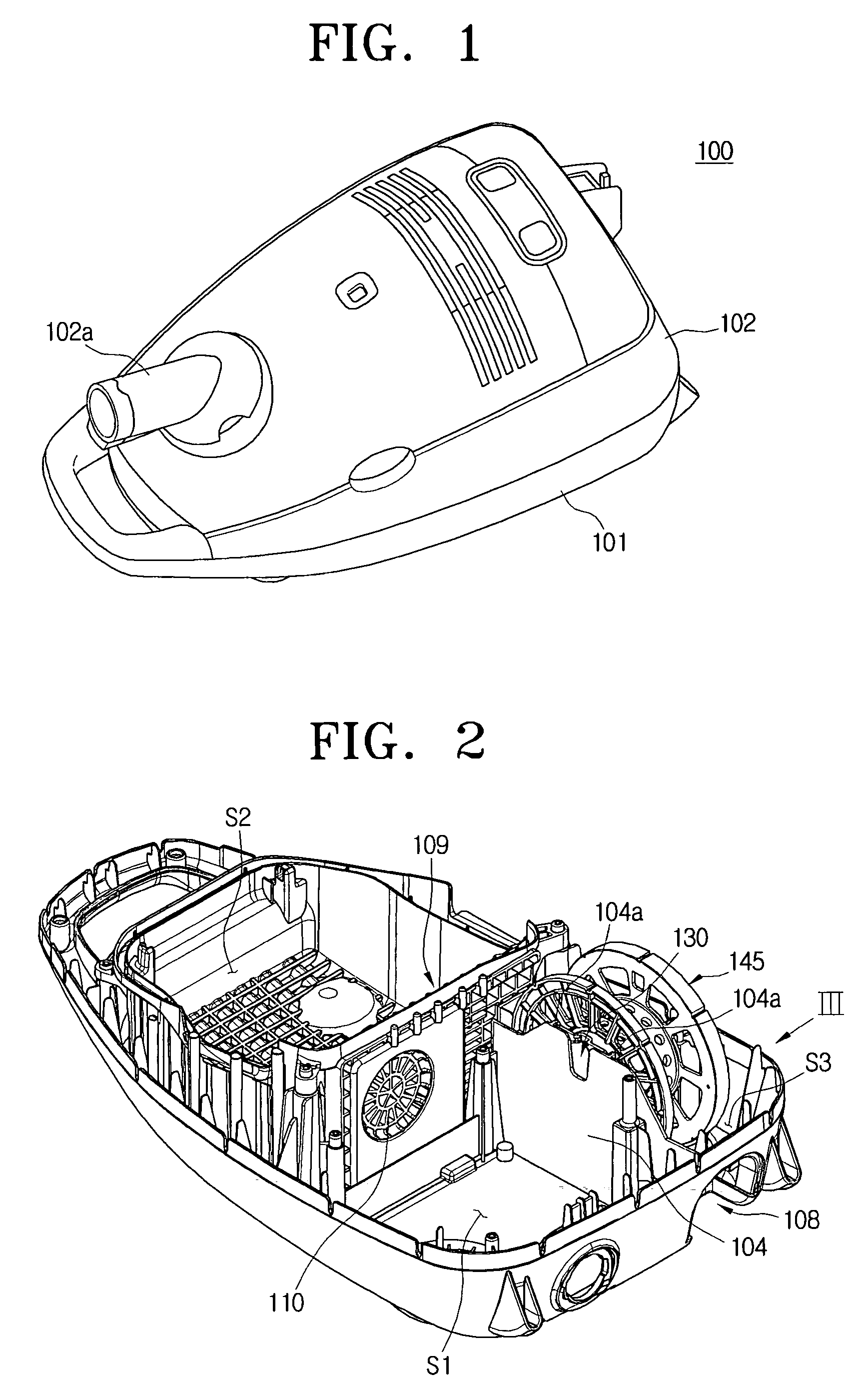
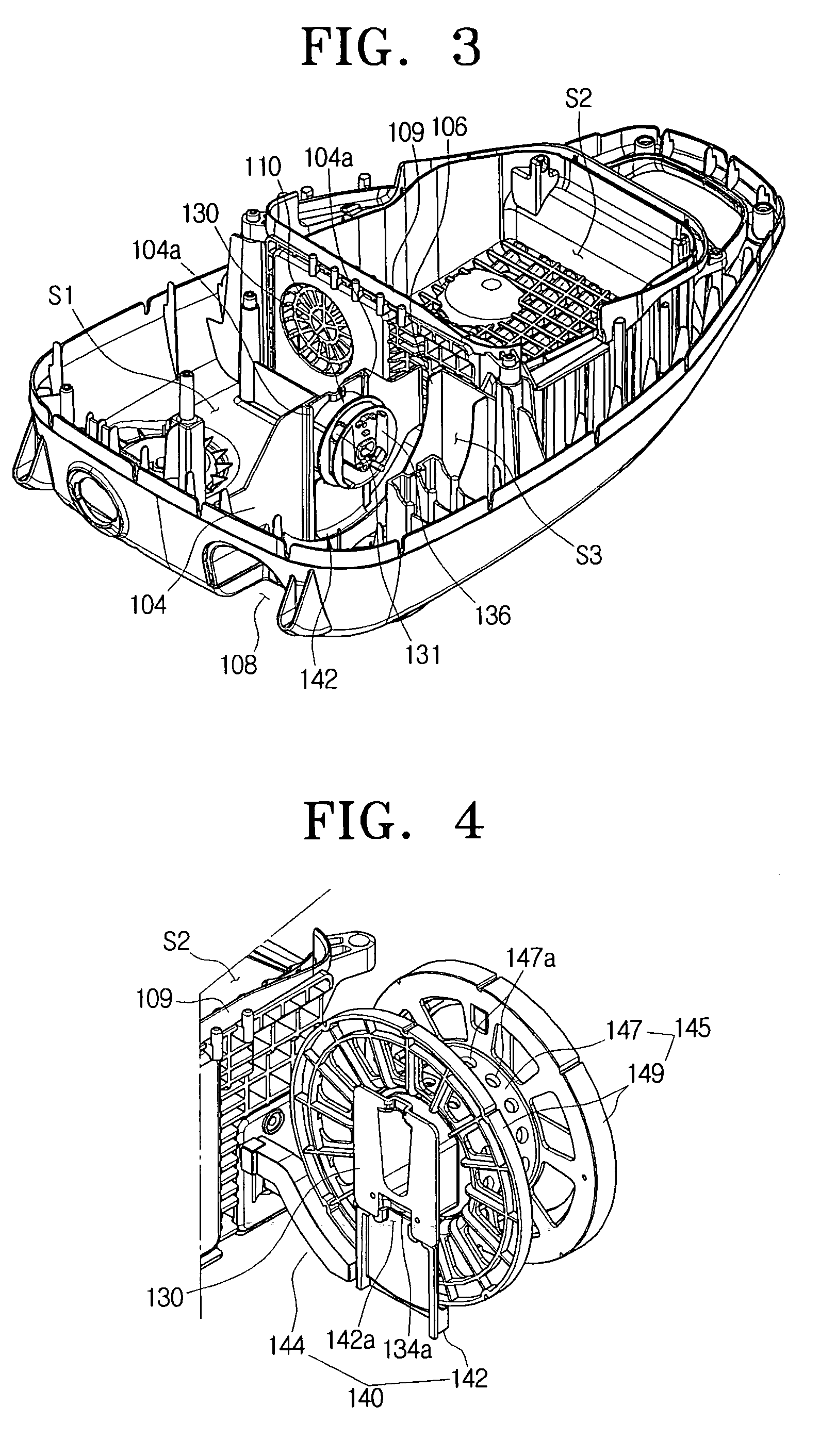
[0023]Referring to FIGS. 1 and 2, the main body 100 of the vacuum cleaner includes a bottom casing 101 and a top casing 102. The top casing 101 is provided with a flexible hose connector 102a to be connected with a flexible hose (not illustrated). The flexible hose allows a suction port assembly (not illustrated) to be fluidly communicated with a contaminants collecting chamber S2 so that contaminants laden air enters the contaminants collecting chamber S2 through the flexible hose. The bottom casing 101 is provided with an isolating wall 109 having a predetermined height. When the bottom casing 101 is coupled to the top casing 102, the contaminants collecting chamber S2 is formed in front of the isolating wall 109. Also, the bottom casing 101 is provided with a first pa...


PUM


Abstract

A power cord cooling apparatus disposed in a cord reel chamber formed inside a main body of the vacuum cleaner to cool a power cord wound around a cord reel, wherein the power cord cooling apparatus allows outside air to enter the cord reel chamber, to contact the power cord wound around the cord reel, and to be discharged outside the cord reel chamber via a center space in the cord reel.

Description

CROSS-REFERENCE TO RELATED APPLICATIONS[0001]This application claims the benefit under 35 U.S.C. §119(a) from Korean Patent Application No. 2007-96082, filed Sep. 20, 2007, in the Korean Intellectual Property Office, the disclosure of which is incorporated herein by reference in its entirety.FIELD OF THE INVENTION[0002]The present invention relates to a vacuum cleaner. More particularly, the present invention relates to a power cord cooling apparatus that allows outside air to flow through a cord reel that is disposed inside the main body of a vacuum cleaner for cooling a power cord wound around the cord reel.BACKGROUND OF THE INVENTION[0003]Generally, a vacuum cleaner is an appliance that sucks contaminants from a surface to be cleaned, separates the contaminants using a contaminants collecting apparatus, and discharges cleaned air outside. A vacuum cleaner typically includes a power cord that will be connected with an external commercial electric power source to receive electric p...

Claims


Application Information

Patent Timeline
IPC IPC(8): B65H75/44
CPCA47L9/26
Inventor CHO, YOUNG-JUNKIM, TAK-SOO
Owner SAMSUNG GWANGJU ELECTRONICS CO LTD
Why Eureka
Try Eureka