Motor unit having cooling channel

Active Publication Date: 2014-06-19
HYUNDAI MOTOR CO LTD +1
View PDF8 Cites 5 Cited by
  • Summary
  • Abstract
  • Description
  • Claims
  • Application Information

AI Technical Summary

Benefits of technology

The present invention provides a motor unit with a cooling channel that improves cooling efficiency for the driving motor. By using a curved flow channel changing portion, the overall flow resistance of the coolant is reduced, leading to increased cooling efficiency. Additionally, the inner and outer protrusion portions of the cooling channel are alternated, creating inner and outer recesses between them, which increases the overall effective cooling area and further enhances the overall cooling efficiency of the motor unit.

Problems solved by technology

Thus, if a heat dissipation area of a water cooling structure (which may include a jacket) formed within a motor is small, the coolant does not flow smoothly, thus degrading cooling performance.

Method used


Image

  • Motor unit having cooling channel
  • Motor unit having cooling channel
  • Motor unit having cooling channel

Examples


Embodiment Construction

[0028]An exemplary embodiment of the present invention will hereinafter be described in detail with reference to the accompanying drawings.

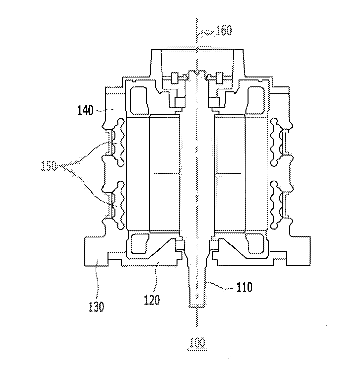
[0029]FIG. 1 is a schematic cross-sectional view of a motor unit having a cooling channel according to an embodiment of the present invention.

[0030]Referring to FIG. 1 a motor unit 100 includes a motor shaft 110, a rotor 120, a stator 130, and a motor housing 140. A cooling channel 150 is formed within the motor housing 140 along an outer circumference of the motor housing 140.

[0031]The motor shaft 110 is installed in the motor housing 140 such that it is rotatable along a virtual rotational shaft or axis 160, and the rotor 120 is fixed to an outer circumferential surface of the motor shaft 110.

[0032]The stator 130 is fixedly installed on an inner circumferential surface of the motor housing 140 to cover an outer circumferential surface of the rotor 120, and the stator 130 and the rotor 120 are disposed such that an inner circumferential surface ...


PUM


Abstract

A motor unit for a vehicle is provided with a cooling channel cooling channel formed within a motor housing of the motor unit, and forming a flow channel that allows coolant to flow through the flow channel. The cooling channel includes: a supply channel portion having an inlet; an exhaust channel portion having an outlet; and a flow channel changing portion connecting the supply channel portion and the exhaust channel portion to allow a coolant supplied through the inlet of the supply channel portion to be discharged through the outlet of the exhaust channel portion, where at least one of inner protrusion portions and outer protrusion portions are formed on an inner circumferential surface and an outer circumferential surface, respectively, of the supply channel portion or the exhaust channel portion, protruding toward the motor shaft, and extending in a circumferential direction.

Description

CROSS-REFERENCE TO RELATED APPLICATION[0001]This application claims under 35 U.S.C. §119(a) priority to and the benefit of Korean Patent Application No. 10-2012-0148701 filed in the Korean intellectual Property Office on Dec. 18, 2012, the entire contents of which are incorporated herein by reference.BACKGROUND[0002](a) Field of the Invention[0003]The present invention relates to a motor unit having a cooling channel capable of cooling a high temperature unit by using a coolant (or cooling water) in a high output electric motor for driving a vehicle, thus enhancing cooling efficiency and increasing operational stability.[0004](b) Description of the Related Art[0005]Generally, a motor structure of an electric vehicle includes a shaft for supporting a rotor, the rotor being rotatably supported by the shaft, a stator fixedly positioned to face the rotor, and a motor housing in which the stator is press-fit, the motor housing positioned to face the rotor for protecting and supporting th...

Claims


Application Information

Patent Timeline
IPC IPC(8): H02K9/00
CPCH02K5/203H02K9/19H02K2205/09B60K2001/006
Inventor HAN, DONGYEONSEO, YOUNG JINCHO, HYOUNGJUNJUNG, MYEONG KYU
Owner HYUNDAI MOTOR CO LTD
Why Eureka
Try Eureka