Thermal treatment furnace

Active Publication Date: 2019-01-10
DAIDO STEEL CO LTD
View PDF3 Cites 2 Cited by
  • Summary
  • Abstract
  • Description
  • Claims
  • Application Information

AI Technical Summary

Benefits of technology

The present invention provides a thermal treatment furnace that improves cooling for thin metal sheets during and after thermal treatment. The furnace allows for easy selection of various cooling rates and can cool the sheet while it is conveyed horizontally and floated by air.

Problems solved by technology

However, for example, in order to enhance a cooling rate of a thin metal sheet by an injection of only air (one type of refrigerant), there is a limit due to a pressure of the air or the like.
However, no effective proposal has been made for the above technical problems so far.

Method used


Image

  • Thermal treatment furnace
  • Thermal treatment furnace
  • Thermal treatment furnace

Examples


Embodiment Construction

[0058]Hereinafter, embodiments for performing the present invention will be described.

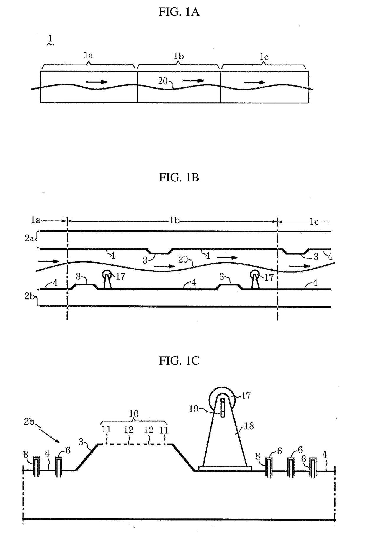
[0059]A thermal treatment furnace 1 of the present invention contains a heating chamber 1a, a thermal treatment chamber 1b, and a cooling chamber 1c, which are linearly arranged along a horizontal direction as illustrated in FIG. 1A. The thermal treatment furnace 1 is configured to be capable of continuously conveying a thin metal sheet 20 in these chambers from the left side to the right side in the drawing while floating the thin metal sheet 20 with air described later, as indicated by arrows in the drawing.

[0060]In the heating chamber la, the thin metal sheet 20 is heated from a room temperature to a required temperature range. In the thermal treatment chamber 1b, the heated thin metal sheet 20 is hardened by quenching, for example. In the cooling chamber 1c, the thin metal sheet 20 after the thermal treatment is cooled to near the room temperature.

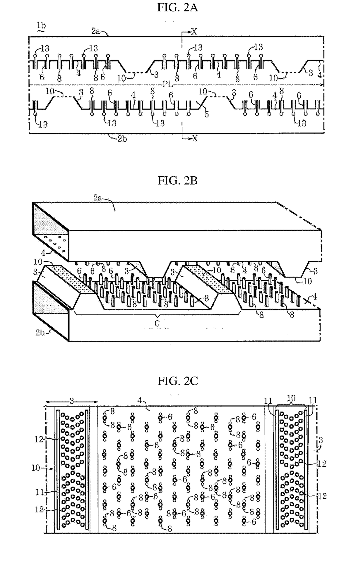
[0061]More specifically, as illustrated in the ...


PUM


Abstract

The present invention relates to a thermal treatment furnace containing a thermal treatment chamber (1b) in which a thin metal sheet (20) is continuously conveyed horizontally while being floated by air (21), in which the thermal treatment chamber (1b) contains a plurality of air injection nozzles (6) and a plurality of mist spray nozzles (8) that are arranged along a pass line (PL) of the thin metal sheet (20) in the thermal treatment chamber (1b), on a lower side and an upper side of the pass line (PL) and so as to be orthogonal to the pass line (PL) in a side view.

Description

TECHNICAL FIELD[0001]The present invention relates to a continuous thermal treatment furnace (so-called floating furnace) in which a thin metal sheet is successively subjected to heating, thermal treatment and cooling while floating the thin metal sheet with air.BACKGROUND ART[0002]For example, for cooling a thermal-treated metal material, which is accommodated and travels along a horizontal direction in a thermal treatment furnace which is continuously operated, the following method for controlling the metal material in the thermal treatment furnace has been proposed (e.g., Patent Document 1). That is, the metal material is controlled such that a trajectory of the metal material between rollers, which support the metal material, is measured by a measuring device and the trajectory obtained based on the measurement result is made to travel between conveying devices of a cooling agent (air, inert gas, liquid, or a mixture of gas and liquid) to be injected for cooling the metal materi...

Claims


Application Information

Patent Timeline
IPC IPC(8): C21D9/00
CPCC21D9/0056C21D9/0018C21D1/667C21D9/46C21D9/63C21D9/0006C21D9/0062F27B9/20F27B9/12F27B2009/124
Inventor KOZUKA, TOSHIYUKIKONDO, YOSHINOBU
Owner DAIDO STEEL CO LTD
Why Eureka
Try Eureka