Rotor

Active Publication Date: 2009-03-26
TOYOTA JIDOSHA KK
View PDF5 Cites 37 Cited by
  • Summary
  • Abstract
  • Description
  • Claims
  • Application Information

AI Technical Summary

Benefits of technology

[0020]As described above, the present invention can suppress

Problems solved by technology

However, in the rotating electric machine disclosed in Japanese Patent Laying-Open No. 2004-104962, a space between the magnet and the roto

Method used


Image

  • Rotor
  • Rotor
  • Rotor

Examples


Embodiment Construction

[0030]Embodiments of a rotor according to the present invention will now be described. The same or corresponding portions bear the same reference numbers, and description thereof may not be repeated.

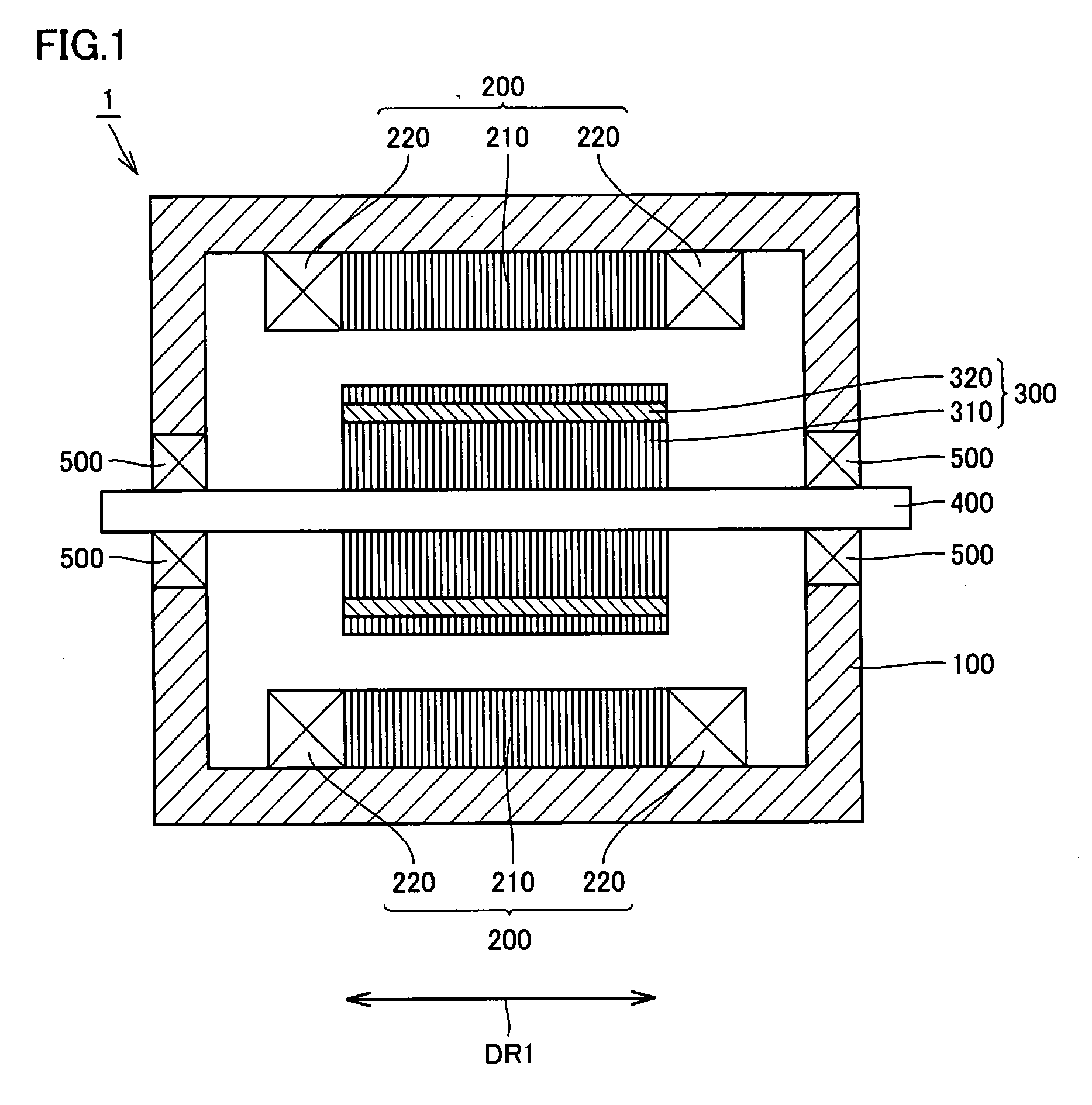
[0031]FIG. 1 is a cross section showing a rotating electric machine including a rotor according to an embodiment of the present invention. Referring to FIG. 1, a rotating electric machine 1 that is a motor and / or a generator includes a stator 200 arranged in a housing 100 having a stator-accommodating portion, a rotor 300, a rotary shaft 400 and bearings 500.

[0032]Stator 200 has an annular stator core 210 and a stator coil 220. Stator core 210 consists of plate-like members which is formed of a magnetic material such as iron or iron alloy. Stator core 210 is provided on its inner peripheral surface with a plurality of teeth (not shown) and slots (not shown) that are concavities formed between the teeth. The slots open on the inner peripheral side of stator core 210.

[0033]Stator coil 220 ...


PUM


Abstract

A rotor is provided with a rotor core, a magnet inserted into the rotor core and a filling portion arranged in a space between the rotor core and the magnet. The space between the rotor core and a radially outer side surface of the magnet has a uniform width in a central portion (portion (A)) with respect to a width direction (of arrow (DR4)) of the magnet. A width of the space in an end portion (portion (B)) with respect to the width direction (of arrow (DR4)) of the magnet is larger than that of the space in the portion (A).

Description

TECHNICAL FIELD[0001]The present invention relates to a rotor, and particularly to a rotor having magnets inserted into a rotor core.BACKGROUND ART[0002]A rotor having magnets inserted into a rotor core has been known.[0003]For example, Japanese Patent Laying-Open No. 2004-104962 has disclosed a rotating electric machine provided with a rotor including a pair of magnet insertion holes spaced from each other by an opposition distance that gradually increases as the position moves toward an outer periphery of a rotor core, and also including permanent magnets fixedly inserted into the magnet insertion holes, respectively.[0004]Japanese Patent Laying-Open No. 2001-352702 has disclosed a rotating electric machine, in which a permanent magnet inserted into a rotor is supported at three points by an inner wall surface of a magnet insertion hole on a plane perpendicular to the insertion direction of the permanent magnet.[0005]However, in the rotating electric machine disclosed in Japanese ...

Claims


Application Information

Patent Timeline
IPC IPC(8): H02K1/27
CPCH02K1/2766
Inventor HATTORI, HIROYUKITAKEHARA, AKIHIDE
Owner TOYOTA JIDOSHA KK
Why Eureka
Try Eureka