Optical Projection System

a projection system and optical technology, applied in the field of optical projection systems, can solve the problems of severely degrading the resultant image quality, wide angle optical projection lenses are limited in the view angles they provide,

Active Publication Date: 2009-03-26
YOUNG OPTICS
View PDF9 Cites 7 Cited by
  • Summary
  • Abstract
  • Description
  • Claims
  • Application Information

AI Technical Summary

Benefits of technology

[0008]The present invention is to provide an optical projection system that is thin, light an

Problems solved by technology

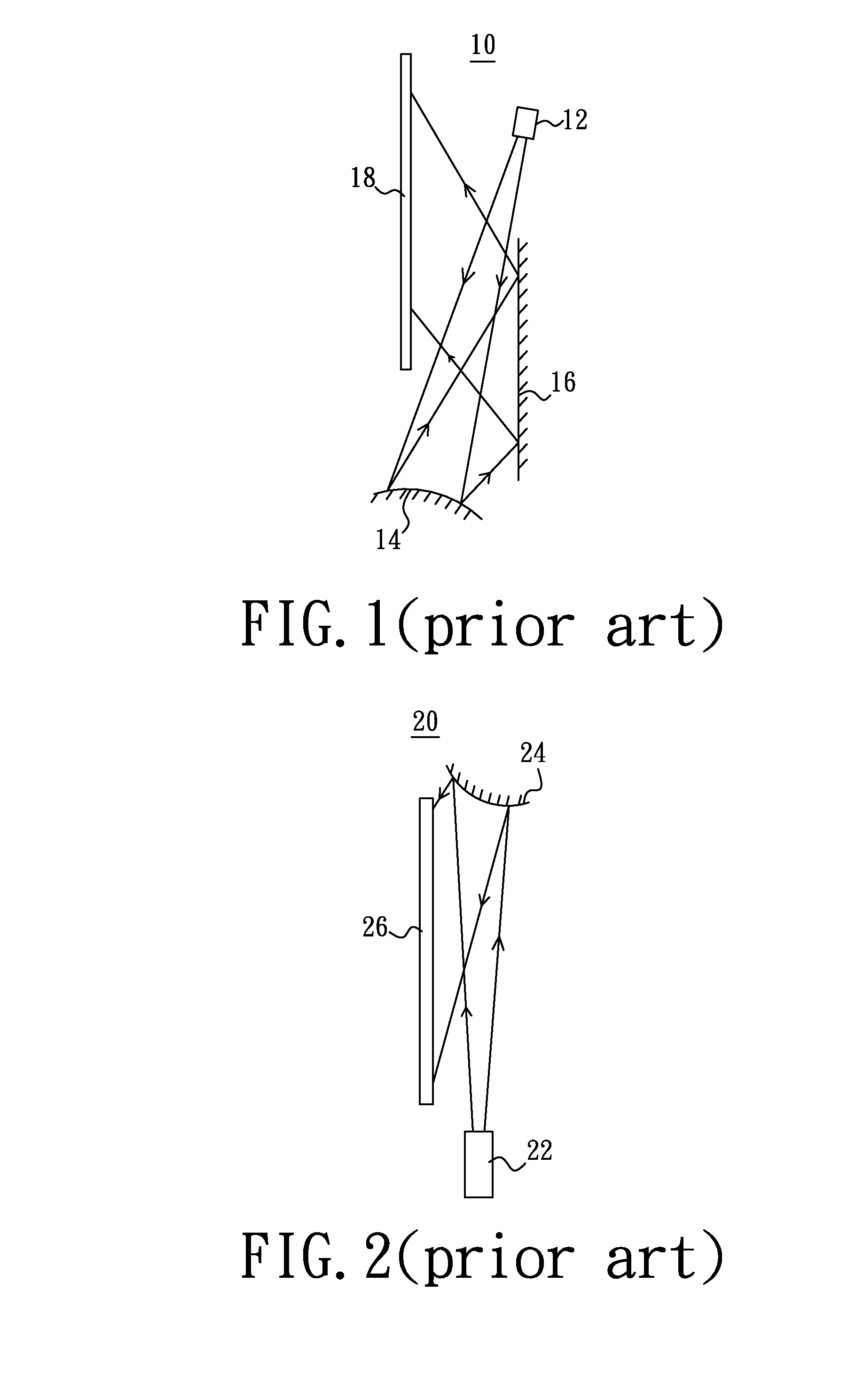
Wide angle optical projection lenses capable of projecting images in a wide angle have been used to reduce the overall thickness of the optical projection system, but the wide angle optical projection lenses are limited in the view angles they provide.
Although the overall volumes of

Method used


Image

  • Optical Projection System
  • Optical Projection System
  • Optical Projection System

Examples


Embodiment Construction

[0020]In the following detailed description of the preferred embodiments, reference is made to the accompanying drawings which form a part hereof, and in which are shown by way of illustration specific embodiments in which the invention may be practiced. In this regard, directional terminology, such as “top,”“bottom,”“front,”“back,” etc., is used with reference to the orientation of the Figure(s) being described. The components of the present invention can be positioned in a number of different orientations. As such, the directional terminology is used for purposes of illustration and is in no way limiting. On the other hand, the drawings are only schematic and the sizes of components may be exaggerated for clarity. It is to be understood that other embodiments may be utilized and structural changes may be made without departing from the scope of the present invention. Also, it is to be understood that the phraseology and terminology used herein are for the purpose of description an...


PUM


Abstract

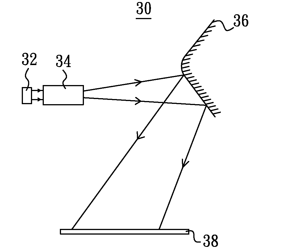
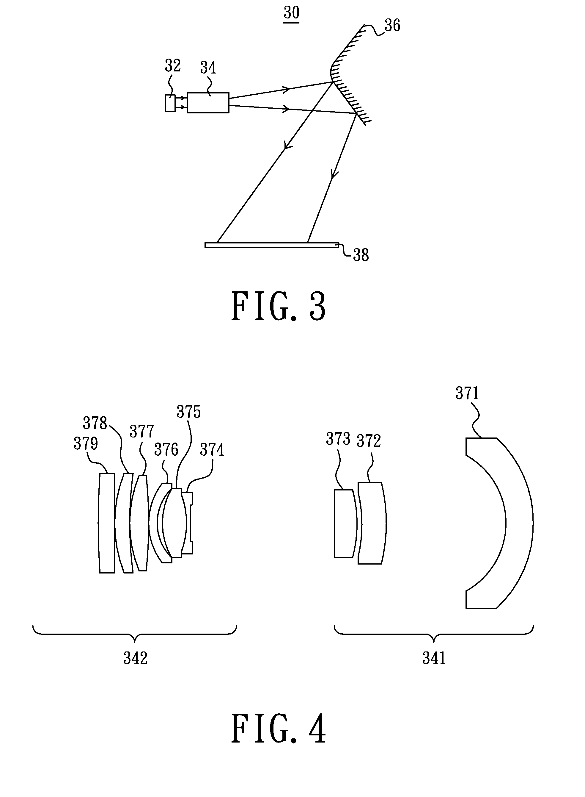
An optical projection system includes an image generation element, a projection lens set for receiving an image from the image generation element, refracting the image and projecting the image out, and a reflector for reflecting the image from the projection lens set and projecting the image to a screen. The projection lens set includes an aspherical lens with a distortion coefficient larger than 0.5 for producing a pincushion distortion of the image and several other lenses, and the absolute value of the sum of the distortion coefficients of the other lenses are less than the distortion coefficient of the aspherical lens. The reflector produces a barrel distortion to the image for compensating a pincushion distortion of the image produced by the projection lens set.

Description

BACKGROUND OF THE INVENTION[0001]1. Field of the Invention[0002]The present invention relates to an optical projection system, and more particularly to an optical projection system that is thin, light and capable of controlling a distortion of an image projected by the optical projection system.[0003]2. Description of the Related Art[0004]An optical projection system generally includes a light source capable of generating a light beam, a parabola reflector capable of reflecting the light beam, an illumination lens capable of compressing the light beam, a light valve capable of converting the light beam into an image in response to an electrical image signal, an optical projection lens capable of magnifying and projecting the image and a screen capable of displaying the image.[0005]A basic working principle of the optical projection system is as follows. First, the light source generates a light beam. The light beam is reflected by the parabola reflector and projected on the illumina...

Claims


Application Information

Patent Timeline
IPC IPC(8): G03B21/28G02B27/18
CPCG02B13/18G03B21/28G02B27/0025
Inventor CHEN, JUNG-YAOLAI, CHING-LUNG
Owner YOUNG OPTICS
Why Eureka
Try Eureka