Unlock instant, AI-driven research and patent intelligence for your innovation.

OFDM demodulation device

Active Publication Date: 2009-03-26
LAPIS SEMICON CO LTD
View PDF4 Cites 11 Cited by
  • Summary
  • Abstract
  • Description
  • Claims
  • Application Information

AI Technical Summary

Benefits of technology

[0010]Therefore, the present invention has been made in view of the above problems, and it is an object of the invention to provide a transmission path state estimator that can highly reliably estimate transmission path states and to provide an OFDM demodulation device that includes the transmission path state estimator and can perform correct demodulation operations according to changes of transmission path states.
[0016]Thus, the transmission path state estimator according to the invention can highly reliably estimate transmission path states from the correlation signal waveform. In addition, the demodulation device according to the invention can perform correct demodulation operations according to changes of transmission path states by switching between operation modes according to the transmission path state estimation.

Problems solved by technology

However, there are problems such as a reduction in the correlation value, failing to achieve time synchronization, and degradation of reception characteristics due to variations of transmission path conditions when reception power is low, when the influence of fading and multipath is high, or when a narrow-band noise signal is included in a received band.

Method used


Image

  • OFDM demodulation device
  • OFDM demodulation device
  • OFDM demodulation device

Examples


first embodiment

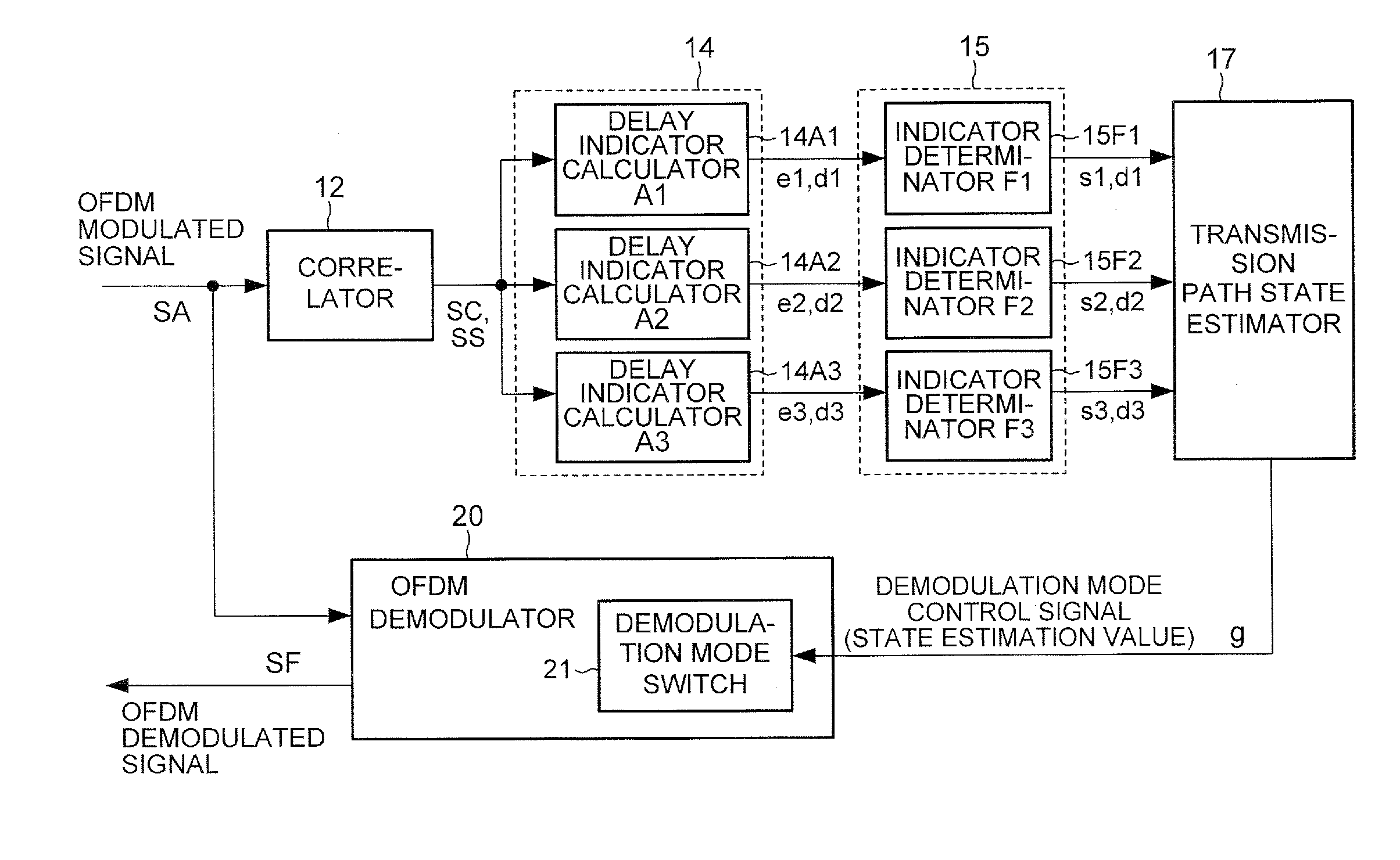
[0028]FIG. 1 schematically illustrates an example configuration of an OFDM demodulation device 10 according to a first embodiment of the invention.

[0029]A received OFDM modulated signal SA is input to a correlator 12. The correlator 12 generates a correlation signal SC based on the OFDM modulated signal SA. The correlator 12 also generates an OFDM-symbol-period synchronization signal SS.

[0030]The correlation signal SC and the synchronization signal SS are provided to a delay indicator calculator 14. The delay indicator calculator 14 calculates an indicator or indicator value indicating a multipath delay, which will be referred to as a multipath indicator or indicator value, based on the correlation signal SC and the synchronization signal SS. The calculated delay indicator is provided to an indicator determinator 15.

[0031]The delay indicator calculator 14 is constructed so as to calculate a plurality of delay indicators and the indicator determinator 15 is constructed so as to gener...

second embodiment

[0130]FIG. 6 schematically illustrates an example of the OFDM demodulation device 10 according to a second embodiment of the invention. In this embodiment, the OFDM demodulation device 10 further includes a fourth delay indicator calculator (A4) 14A4 and a fourth indicator determinator (F4) 15F4.

[0131]The fourth delay indicator calculator 14A4 detects gradients (slopes) of a trapezoidal waveform according to a correlation signal SC in each symbol duration (duration (j), j=1, 2, . . . ) as shown in FIG. 7.

[0132]More specifically, in the trapezoidal correlation waveform, the correlation signal level increases as a main path signal is received, forming a peak M, and decreases subsequent to a peak S corresponding to a delay path signal. The fourth delay indicator calculator 14A4 detects positive and negative gradients of the signal waveform corresponding to main and delay path signals of the correlation signal. More specifically, the fourth delay indicator calculator 14A4 determines poi...


PUM


Abstract

A delay indicator calculator calculates at least two of a first delay indicator indicating a delay time determined based on a correlation value having a predetermined difference from the maximum value of the correlation signal, a second delay indicator indicating a change of a delay time determined based on time during which the correlation signal has no less than a predetermined value, and a third delay indicator indicating a change of a time difference between main and delay path peaks. An estimator generates a state estimation of the transmission path based on the probabilities of the at least two delay indicator values exceeding respective reference values for a plurality of symbols.

Description

BACKGROUND OF THE INVENTION[0001]1. Field of the Invention[0002]The present invention relates to an Orthogonal Frequency Division Multiplexing (OFDM) demodulation apparatus that demodulates OFDM-modulated signals.[0003]2. Description of the Related Art[0004]OFDM modulation, which has a variety of advantages, has been widely used as a multicarrier transmission method for terrestrial digital broadcasting or wireless LAN.[0005]Since OFDM modulation uses a plurality of periodic waveforms, adding a copy of part of an OFDM modulation waveform as a repeated waveform increases resistance in multipath reception. The added waveform part is generally referred to as a guard interval (GI) or a cyclic prefix.[0006]A conventional correlator determines a correlation between a received signal and a part of the received signal corresponding to a guard interval delayed by an effective OFDM symbol. In conventional time synchronization methods, a time position at which the correlation value output from ...

Claims


Application Information

Patent Timeline
IPC IPC(8): H04L27/28H04L27/06
CPCH04L25/0216H04L27/2649H04L25/0222
Inventor ICHIKAWA, TOMOYUKI
Owner LAPIS SEMICON CO LTD
Features
  • R&D
  • Intellectual Property
  • Life Sciences
  • Materials
  • Tech Scout
  • Unparalleled Data Quality
  • Higher Quality Content
  • 60% Fewer Hallucinations
Learn More