Image display system, apparatus and method

a technology of image display and apparatus, applied in the field of image display system, can solve the problems of high system cost, unsatisfactory follow-up observation, labor-intensive for doctors to retrieve the corresponding past image, etc., and achieve the effect of not raising the system cos

Inactive Publication Date: 2009-03-26
FUJIFILM CORP
View PDF6 Cites 35 Cited by
  • Summary
  • Abstract
  • Description
  • Claims
  • Application Information

AI Technical Summary

Benefits of technology

[0026]Since the corresponding past image to the designated present image is extracted from the past data with reference to the correspondence data that shows correspondence between the past images and the present images with respect to their imaging positions, and the present image and the corresponding past image are displayed on the same display device in the comparison mode, the doctor in charge of image interpretation can easily compare the present image with the corresponding past image. Even if the test device has gone through the follow-up examinations many times and thus there are a plural number of corresponding past images to the designated present image, the present and past images may be displayed in turn on the same display device. Therefore, the individual images are displayed in a visible manner without raising the system cost.

Problems solved by technology

Therefore, it has been labor-consuming for the doctors to retrieve the corresponding past image or images from among a large number of past images.
However it is not always satisfactory for the follow-up observation to compare the images taken around the key image area.
Then, the system would be expensive.
Although the latter prior art discloses displaying a plurality of images on the same divided screen of the monitor, the reduced size of the images in the respective divisions of the screen is inconvenient for the image interpretation.

Method used


Image

  • Image display system, apparatus and method
  • Image display system, apparatus and method
  • Image display system, apparatus and method

Examples


Embodiment Construction

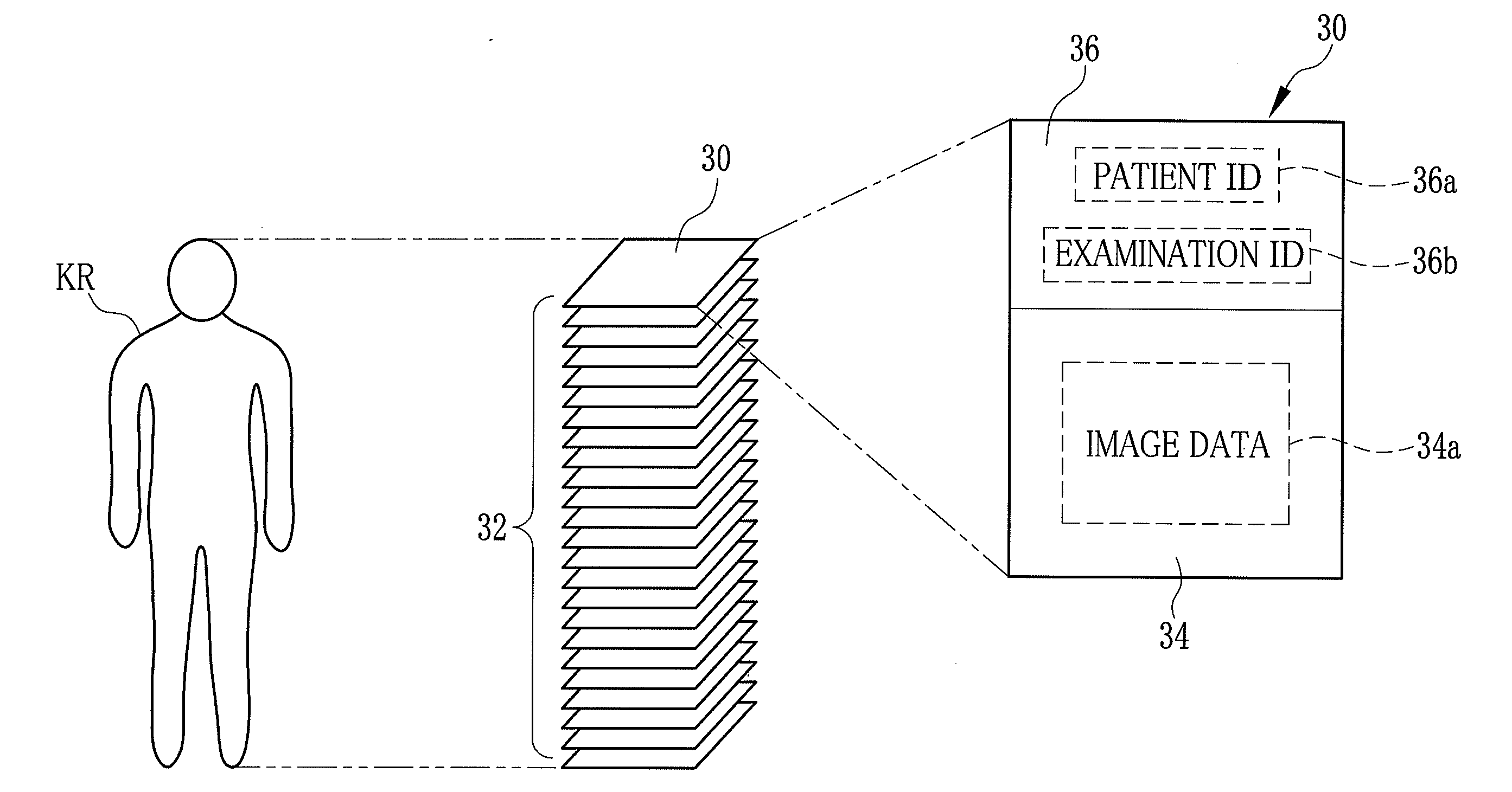
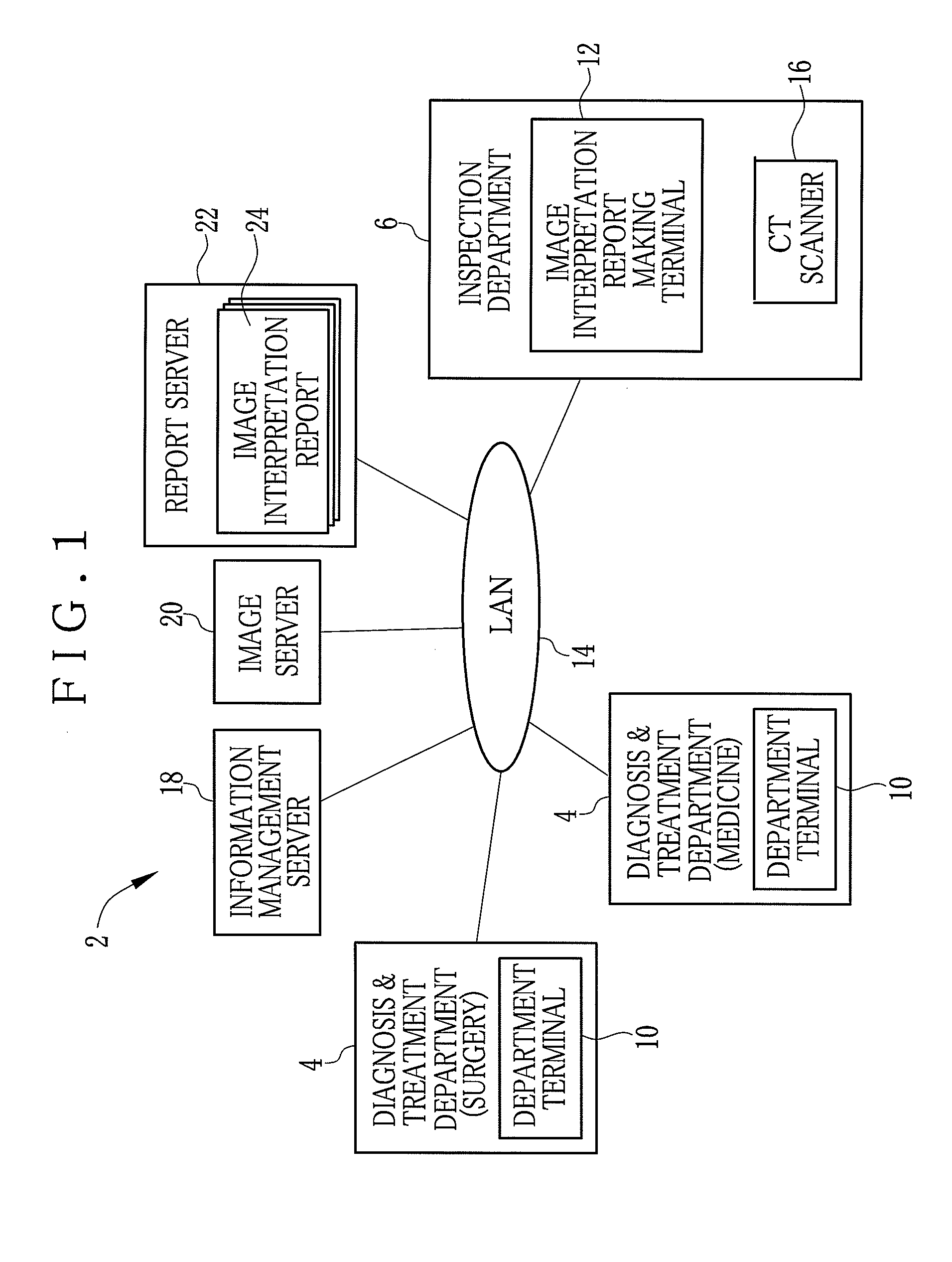
[0046]FIG. 1 shows a medical network system 2, which is installed in a medical facility like a hospital, as an embodiment of the image interpretation report making system of the present invention. The medical network system 2 consists of a plurality of department terminals 10 that are installed in respective diagnosis and treatment departments 4 like those for surgery, medicine etc., an image interpretation report making terminal 12 that is installed in an inspection department 6 like that for radiography, and a local area network (LAN) 14 interconnecting these terminals 10 and 12. To the LAN 14 are also connected a CT scanner 16, which is installed in the inspection department 6, an information management server 18, an image server 20 and a report server 22. The information management server 18 manages a variety of information inside the medical facility. The image server 20 is a data storage device storing various medical images including slice images 30 taken by the CT scanner 16...


PUM


Abstract

When a series of present images have been taken at a follow-up examination of a patient, correspondence data is produced, showing correspondence between the respective present images and past images that were taken at past examinations of the same patient under similar condition. The correspondence data is stored in association with the present images. In a normal mode of an image interpretation making terminal, a designated one of the present images is displayed on a monitor. When a comparison mode is selected, such past images that correspond to the designated present image are retrieved from among those taken at the respective past examinations with reference to the correspondence data, so that the present image and the corresponding past images are displayed in turn or in parallel on the monitor.

Description

FIELD OF THE INVENTION[0001]The present invention relates to an image display system for displaying images obtained through at least a past examination as well as images newly obtained through an examination under similar condition to the past examination. The present invention relates also to an image display apparatus and an image display method for the image display system.BACKGROUND OF THE INVENTION[0002]In medical facilities like hospitals, a variety of medical examination apparatuses, such as modalities for CR (computed radiography), CT (computer tomography), MRI (magnetic resonation imaging), PET (positron emission tomography) and ultrasonic diagnosis, have been widely used. Medical images taken by the modalities are used in medical diagnoses, taking an important roll on determining the nature of a condition of a patient.[0003]For the diagnosis based on medical images, doctors of individual diagnosis and treatment departments generally ask a doctor in an inspection department...

Claims


Application Information

Patent Timeline
Patent Type & Authority Applications(United States)
IPC IPC(8): G06K9/00
CPCG06F19/321G06F19/3487G06F19/3425G16H15/00G16H30/20G16H30/40G16H80/00
Inventor SAGAWA, MASAFUMI
Owner FUJIFILM CORP
Why Eureka
Try Eureka