Spherical bearing with resin liner and rod end bearing

a technology of resin liner and spherical bearing, which is applied in the direction of sliding contact bearings, mechanical equipment, rotary machine parts, etc., can solve the problems of inability to increase load capacity significantly, damage to spherical bearing, and inability to function as a slide bearing, etc., to achieve the effect of increasing load capacity and ensuring outer ring strength

Inactive Publication Date: 2009-03-26
MINEBEA CO LTD
View PDF10 Cites 17 Cited by
  • Summary
  • Abstract
  • Description
  • Claims
  • Application Information

AI Technical Summary

Benefits of technology

[0014]In the first aspect of the present invention, the concave inner surface means that the inner surface is formed in a manner so that the inner diameter at the center portion of the outer ring is larger than the opening diameter of the opening portion. According to this structure, the opening diameter of the end portion of the outer ring can be smaller than the spherical diameter of the inner ring. The inner ring can be inserted into the outer ring by using the notched portion. Accordingly, the spherical diameter of the inner ring is not limited, and the inner ring can be freely designed.
[0015]The inner diameter of the opening portion of the outer ring is set to be smaller than the spherical diameter of the inner ring. Therefore, when a thrust load is applied, the load applied from the inner ring to the resin liner is supported by a part of the concave surface of the outer ring. In this portion, the resin liner is compressed in the thickness direction, whereby the load capacity depends not only on the shear strength of the resin liner, but also on the compressive strength. Since the compressive strength of the resin liner is larger than the shear strength, the structure which supports the thrust load by the compression of the resin liner as described above, can receive a thrust load larger than a case according to the conventional technique in which the thrust load is supported by using the shear strength of the resin liner. Additionally, when the outer ring is made of a metal which has greater rigidity than that of a resin liner, the bearing can withstand a larger thrust load by receiving the thrust load in the concave surface of the metallic outer ring.
[0016]Since the opening diameter of the end portion of the outer ring can be made smaller than the spherical diameter of the inner ring, it is not necessary to make the clearance between the concave surface inside the outer ring and the convex spherical surface outside the inner ring increasing toward the opening. Therefore, it is possible to adopt a structure wherein the resin liner is not easily forced out to the outside when a thrust load is applied. This is an additional advantage to support a larger thrust load.
[0017]The resin for forming the resin liner is continuously injected into the clearance between the concave surface and the convex spherical surface and the notched portion to fill all the space. Therefore, after the resin has solidified, an integral structure is formed such that a protruding portion connected to the resin liner is fitted in the notched portion. Thus, the resin liner is more strongly secured inside the outer ring, thereby effectively preventing the resin liner from co-rotating with the inner ring. Accordingly, it is not necessary to provide grooves to secure the resin liner inside the outer ring, and even when grooves are provided, the size and the number thereof can be selected so as not to affect the strength of the outer ring.
[0019]According to the third aspect of the present invention, the clearance between the inner ring and the outer ring may decrease from the center portion of the inner surface toward the opening portion of the outer ring. According to this structure, the resin liner can be formed so as to have a thickness distribution such that the resin liner is not easily forced out from the clearance to the outside when a thrust load is applied. Therefore, the bearing can receive a larger thrust load.
[0022]According to the present invention, a spherical bearing with resin liner, in which the load capacity is greatly increased, the outer ring strength is assured, and the co-rotation of resin liner is prevented, can be provided.

Problems solved by technology

That is, the spherical bearing is damaged and can no longer function as a slide bearing.
Therefore, in the spherical bearing shown in FIGS. 9A to 9C, the load capacity cannot be easily increased significantly.
Accordingly, the load capacity cannot be greatly increased.

Method used


Image

  • Spherical bearing with resin liner and rod end bearing
  • Spherical bearing with resin liner and rod end bearing
  • Spherical bearing with resin liner and rod end bearing

Examples


first embodiment

(1) First Embodiment

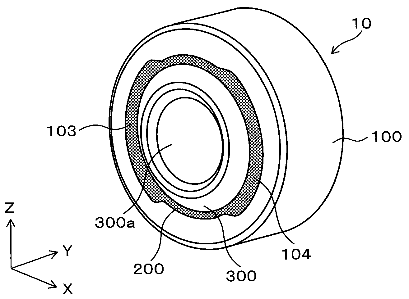
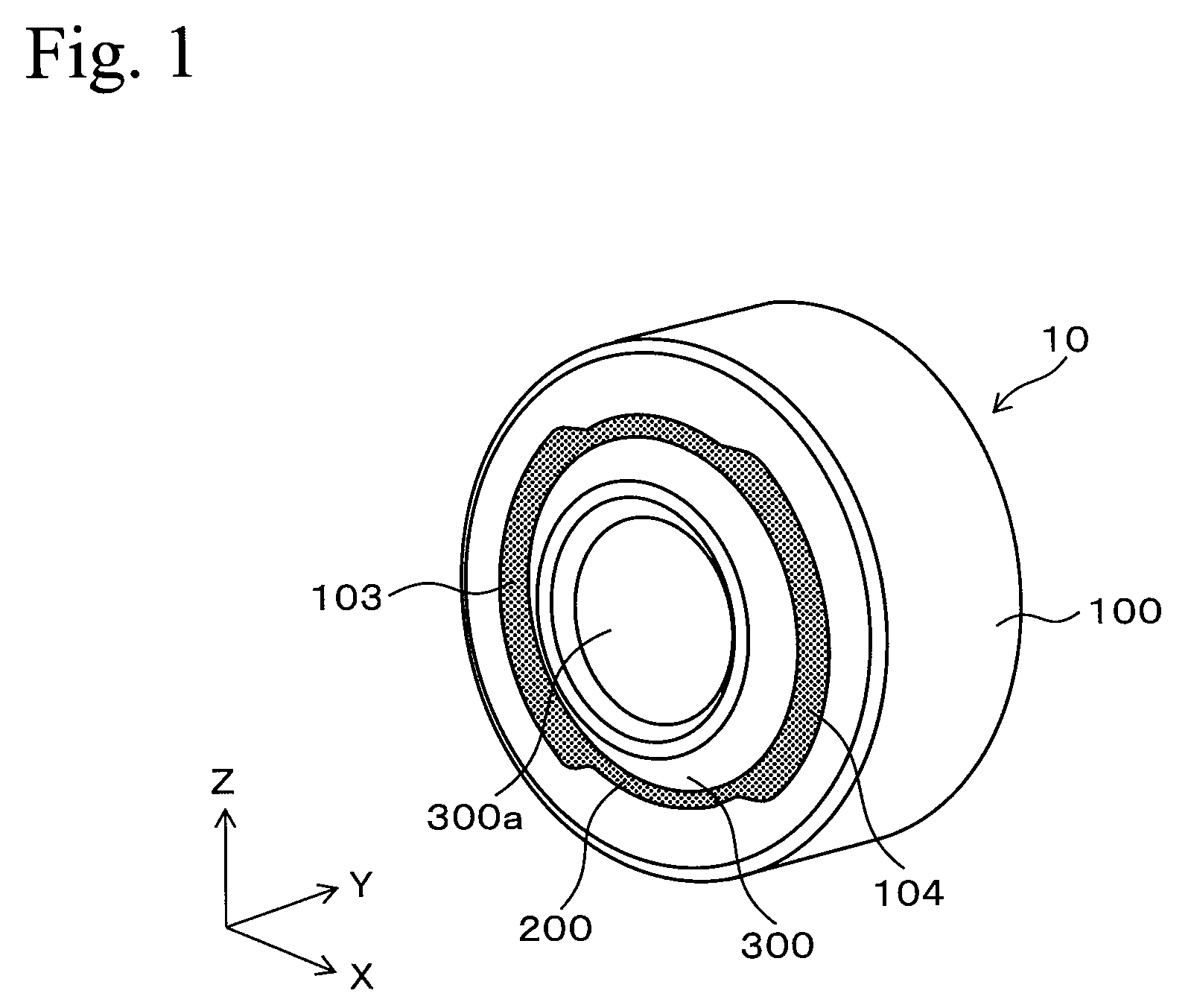
[0032]An embodiment using the present invention will be described hereinafter. FIG. 1 is a perspective view showing a structure of a spherical bearing with resin liner according to the present invention. FIG. 1 shows the spherical bearing 10 with resin liner having a basic structure comprising an inner ring 300 rotatably supported inside an outer ring 100 via a resin liner 200. The outer ring 100 and the inner ring 300 are made of metal in order to ensure the strengths thereof. The materials of the outer ring 100 and the inner ring 300 are not limited to metal as long as the strengths thereof satisfy the requirement. For example, sintered alloy, engineering plastic, or composite material may be used.

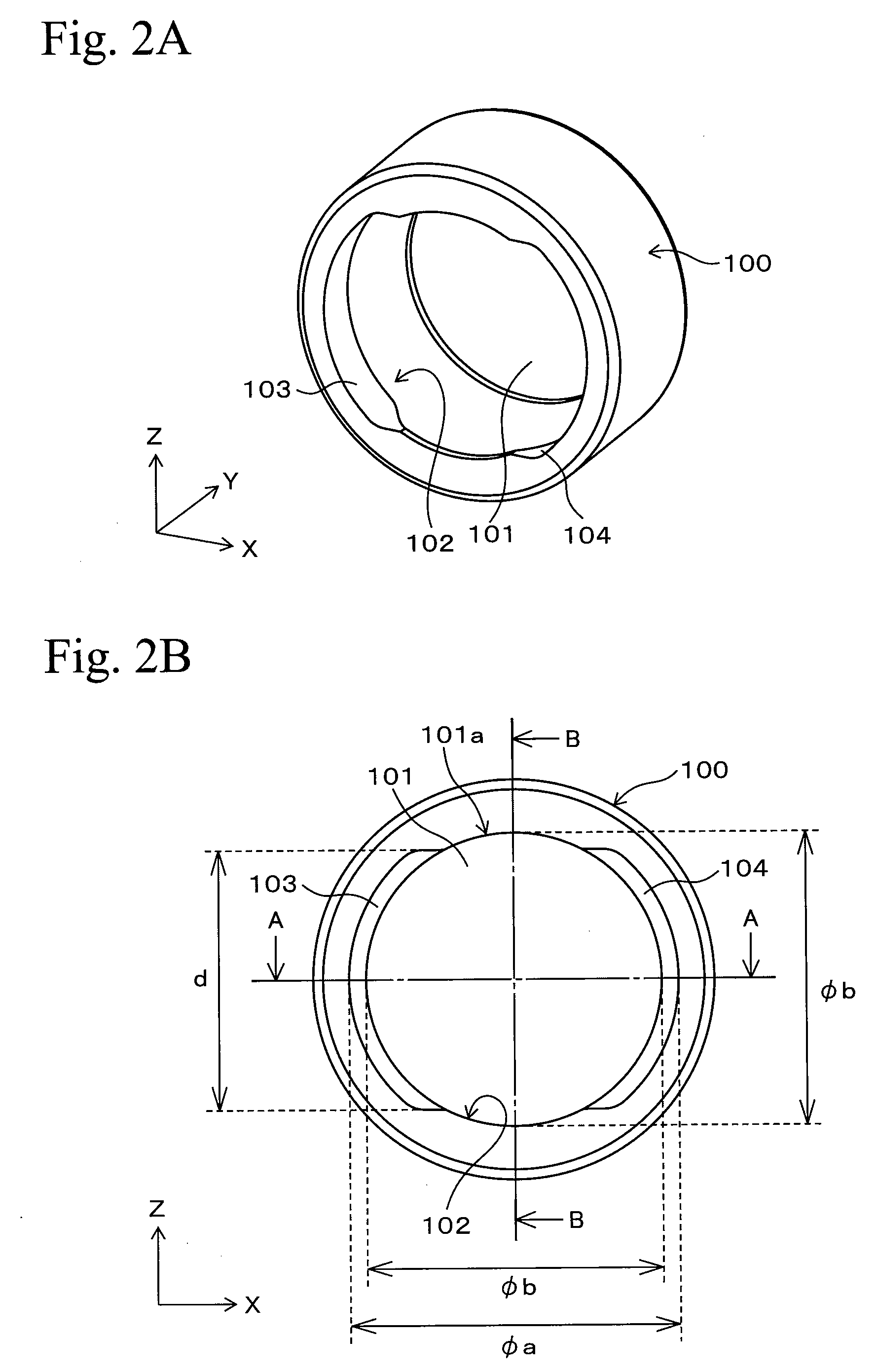
[0033]The spherical bearing 10 with resin liner will now be described in detail. FIGS. 2A and 2B show the outer ring 100, FIG. 2A is a perspective view, and FIG. 2B is the front view. FIG. 2B shows the outer ring 100 of the spherical bearing 10 with resin liner viewed...

second embodiment

(2) Second Embodiment

[0051]The spherical bearing 10 with resin liner shown in FIG. 1 can be applied for a rod end bearing. FIGS. 7A to 7C are perspective views showing the possible structures of rod end bearings. FIG. 7A shows the rod end bearing 700 as an example 1 according to the present invention. The rod end bearing 700 comprises an outer ring 701 with a screw rod extending in the radial direction (a rod member formed with screws) 701 a formed integrally. Inside the outer ring 701, an inner ring 705 is rotatably supported via a resin liner 702, similarly to the case of the first embodiment. In this structure, portions indicated by reference numerals 703 and 704 are formed as notched portions (the figure shows a condition where the resin material for forming the resin liner was injected).

[0052]The rod end bearing 700 shown in FIG. 7A is fixed to a rod member by mounting a screw rod 701a to a counter screw structure (a screw structure that engages with the screw rod 701a) that is...


PUM

PropertyMeasurementUnit
shapeaaaaaaaaaa
inner diameteraaaaaaaaaa
outer diameteraaaaaaaaaa

Abstract

A spherical bearing with resin liner comprises an inner ring, an outer ring, an opening portion, a notched portion, and a resin liner portion. The inner ring has a convex spherical outer surface and a shape in which opposing end portions of a sphere are cut off, and the outer ring has a concave inner surface which faces the outer surface of the inner ring having a predetermined clearance therebetween. The opening portion is provided at the outer ring and has an inner diameter smaller than the outer diameter of the inner ring, and the opening portion communicates with a space surrounded by the inner surface of the outer ring. The notched portion is provided at an edge of the opening portion for inserting the inner ring into the outer ring, and the resin liner portion continuously fills the clearance and the notched portion.

Description

RELATED APPLICATIONS[0001]This application claims priority under 35 U.S.C. §119 to Japanese Patent Application No. JP2007-248688 filed Sep. 26, 2007, the entire content of which is hereby incorporated by reference.BACKGROUND OF THE INVENTION[0002]1. Technical Field[0003]The present invention relates to a spherical bearing with resin liner and a rod end bearing including the spherical bearing capable to support a large thrust load.[0004]2. Background Art[0005]A spherical bearing has a basic structure in which an inner ring having a convex spherical outer surface is slidably supported by an outer ring having a concave spherical inner surface. For example, such spherical bearings are disclosed in Japanese Unexamined Patent Applications Publication Nos. 7-42729 and 6-200931, Japanese Examined Utility Model Application Publication No. 3-20573, and Japanese Unexamined Utility Model Application Publication No. 6-40448.[0006]FIGS. 9A to 9C are cross sectional views showing a structure of a ...

Claims


Application Information

Patent Timeline
Patent Type & Authority Applications(United States)
IPC IPC(8): F16C11/08
CPCF16C11/0614F16C33/20F16C23/045F16C2220/04
Inventor SASAKI, GENOURA, MITSUNORI
Owner MINEBEA CO LTD
Why Eureka
Try Eureka