
Receiver and electronic apparatus using the same

a technology of electronic equipment and receiver, applied in power management, high-level techniques, wireless communication, etc., can solve the problems of degrading and disadvantageous reception quality of receiver 201, and achieve the effect of improving the reception quality of receiver 1

Inactive Publication Date: 2009-03-26
PANASONIC CORP
View PDF11 Cites 12 Cited by
  • Summary
  • Abstract
  • Description
  • Claims
  • Application Information

AI Technical Summary

Benefits of technology

[0027]In this structure, when the frequency of the first local signals fed from the first-local-signal-output terminal to the first-local-signal-input terminal is within the predetermined range from the second frequency band, the second mixing unit uses the second local signals passing the inside of second semiconductor chip 3. Therefore, mixing of the signals of the second frequency band from the communication unit into the second mixing unit can be suppressed. Thus, the receiving quality of receiver 1 can be improved.

Problems solved by technology

As a result, the receiving quality of receiver 201 degrades, disadvantageously.

Method used


Image

  • Receiver and electronic apparatus using the same
  • Receiver and electronic apparatus using the same
  • Receiver and electronic apparatus using the same

Examples


first exemplary embodiment

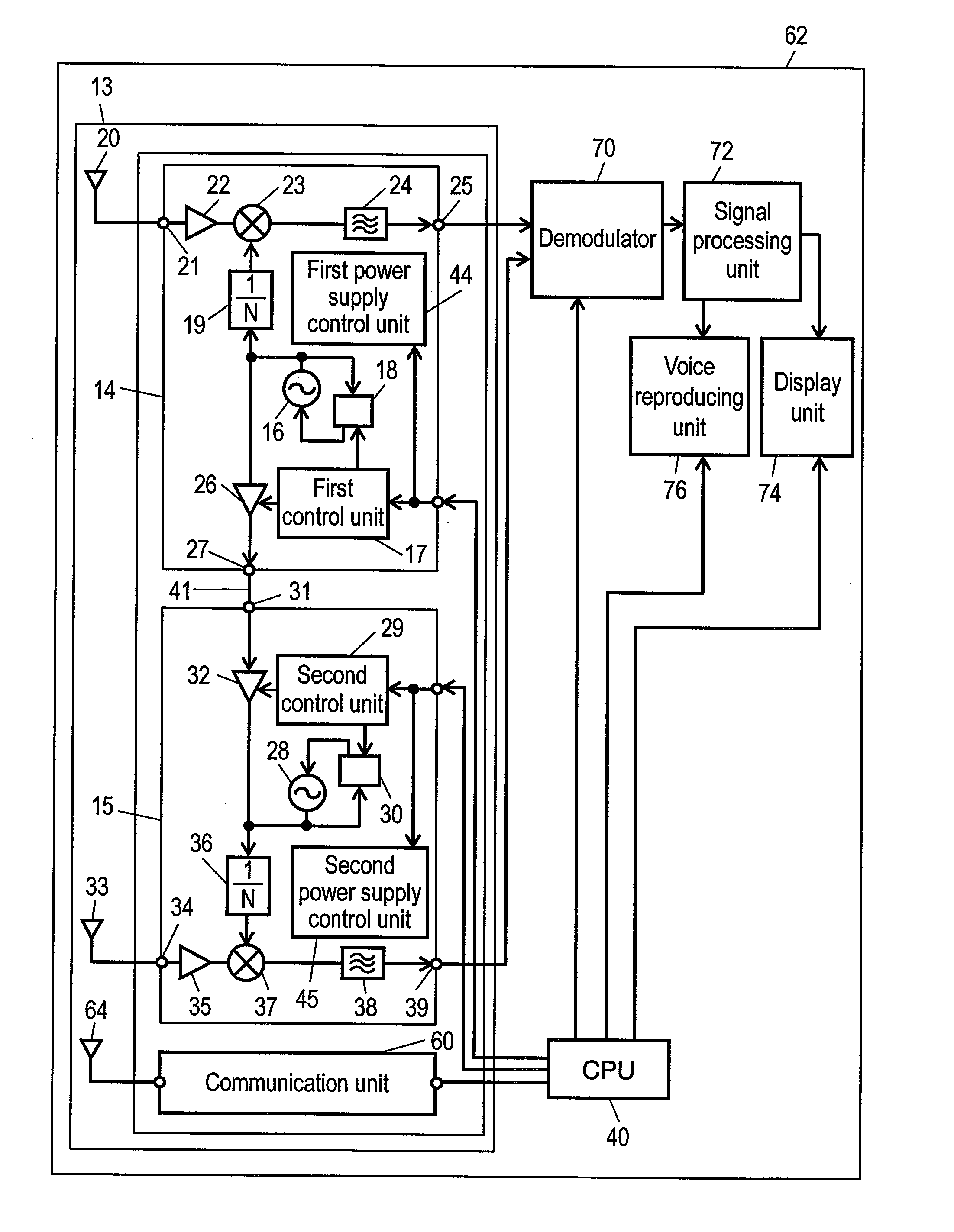
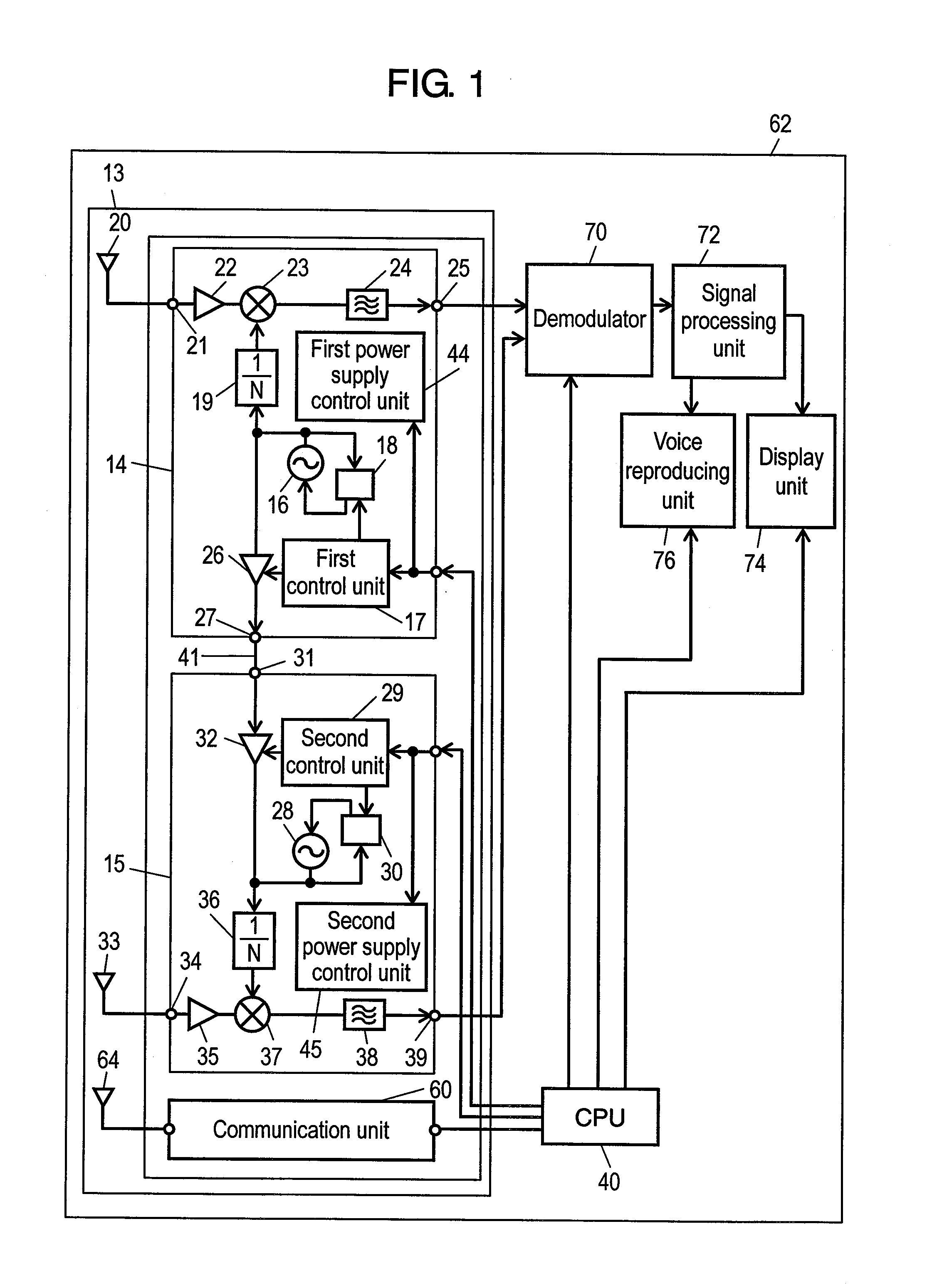
[0083]The first exemplary embodiment of the present invention is described with reference to FIG. 1. FIG. 1 is a block diagram of a receiver in accordance with the first exemplary embodiment of the present invention.

[0084]In FIG. 1, receiver 13 has first semiconductor chip 14 and second semiconductor chip 15 for diversity-receiving signals of a first radio frequency band, and communication unit 60 for performing communication using signals of a second radio frequency band. Electronic apparatus 62 employing receiver 13 has demodulator 70 coupled to the output side of first semiconductor chip 14 and second semiconductor chip 15, and signal processing unit 72 coupled to the output side of demodulator 70. Electronic apparatus 62 also has display unit 74 such as a liquid crystal display and voice reproducing unit 76 such as a speaker that are coupled to the output side of signal processing unit 72. Electronic apparatus 62 also has CPU 40 for controlling the circuit of each block inside i...

second exemplary embodiment

[0112]The second exemplary embodiment of the present invention is described with reference to FIG. 3. FIG. 3 is a block diagram of a receiver in accordance with the second exemplary embodiment of the present invention. Elements similar to those in the first exemplary embodiment are denoted with the same reference marks, and the descriptions of those elements are omitted and the difference is described. In FIG. 3, the second exemplary embodiment is different from the first exemplary embodiment in that third buffer 42 whose input / output direction is opposite to that of first buffer 26 is coupled to first buffer 26 in parallel and fourth buffer 43 whose input / output direction is opposite to that of second buffer 32 is coupled to second buffer 32 in parallel.

[0113]First semiconductor chip 14 has first power supply control unit 44 for selecting whether to turn on or off the individual operation of each of circuit units such as first local oscillator 16, first PLL circuit 18, first buffer...


PUM


Abstract

A receiver has a first semiconductor chip and second semiconductor chip for receiving signals of a first radio frequency band, and a communication unit for performing communication using signals of a second radio frequency band. A second mixing unit in the second semiconductor chip uses second local signals supplied from a second local signal oscillator when the frequency of first local signals fed from a first-local-signal-output terminal to a first-local-signal-input terminal is within a predetermined range from the second frequency band, or uses first local signals supplied from the first-local-signal-input terminal when the frequency of the first local signals fed from the first-local-signal-output terminal to the first-local-signal-input terminal is out of the predetermined range from the second frequency band.

Description

[0001]THIS APPLICATION IS A U.S. NATIONAL PHASE APPLICATION OF PCT INTERNATIONAL APPLICATION PCT / JP2007 / 058429.TECHNICAL FIELD[0002]The present invention relates to a receiver for receiving signals and an electronic apparatus using this.BACKGROUND ART[0003]A conventional receiver will be hereinafter described with reference to FIG. 4. In FIG. 4, conventional receiver 201 has first semiconductor chip 202 and second semiconductor chip 203 for diversity-receiving signals of a first radio frequency band, and a communication unit (not shown) for performing communication using signals of a second radio frequency band. First semiconductor chip 202 has the following elements:[0004]first local oscillator 204 for oscillating first local signals;[0005]first divider 205 for N-dividing the first local signals supplied from first local oscillator 204; and[0006]first mixing unit 206 for frequency-converting the signals of the first radio frequency band using the first local signals supplied from f...

Claims


Application Information

Patent Timeline
Patent Type & Authority Applications(United States)
IPC IPC(8): H04B1/16
CPCH04B1/0082H04W52/0274H04B15/06H04B7/0871Y02D30/70
Inventor FUJII, TAKESHIOZEKI, HIROAKI
Owner PANASONIC CORP
Learn More