Vehicular driving power distribution device

a technology for distribution devices and vehicles, applied in mechanical devices, transportation and packaging, gearing, etc., can solve the problems of increasing the size of the device, unable to generate sufficient torque difference between the right and left driving wheels, etc., and achieve the effect of simple control

Inactive Publication Date: 2009-03-26
TOYOTA JIDOSHA KK
View PDF12 Cites 6 Cited by
  • Summary
  • Abstract
  • Description
  • Claims
  • Application Information

AI Technical Summary

Benefits of technology

[0018]Besides, preferably, torque distribution to the right and left driving wheels can be controlled by controlling the driving power generated by the motor. According to the vehicular driving power distribution device described above, a desired torque Difference can be generated between the right and left driving wheels through a simpl

Problems solved by technology

However, the above-described related art has a drawback that a sufficient torque difference cannot be generated between the right and left driving wheels when the input driving power is relatively small.
Besides, in a type of driving power distribution device in which the entire driving power

Method used


Image

  • Vehicular driving power distribution device
  • Vehicular driving power distribution device
  • Vehicular driving power distribution device

Examples


first embodiment

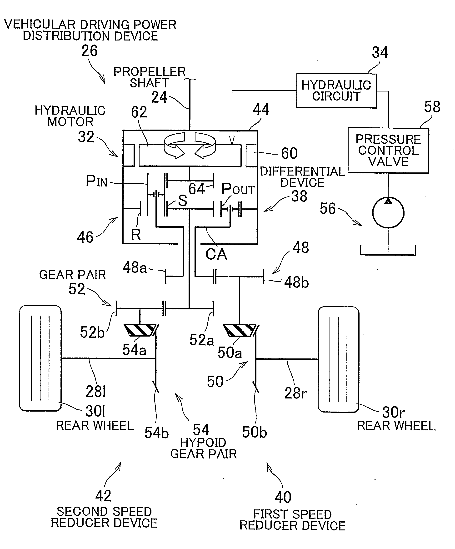
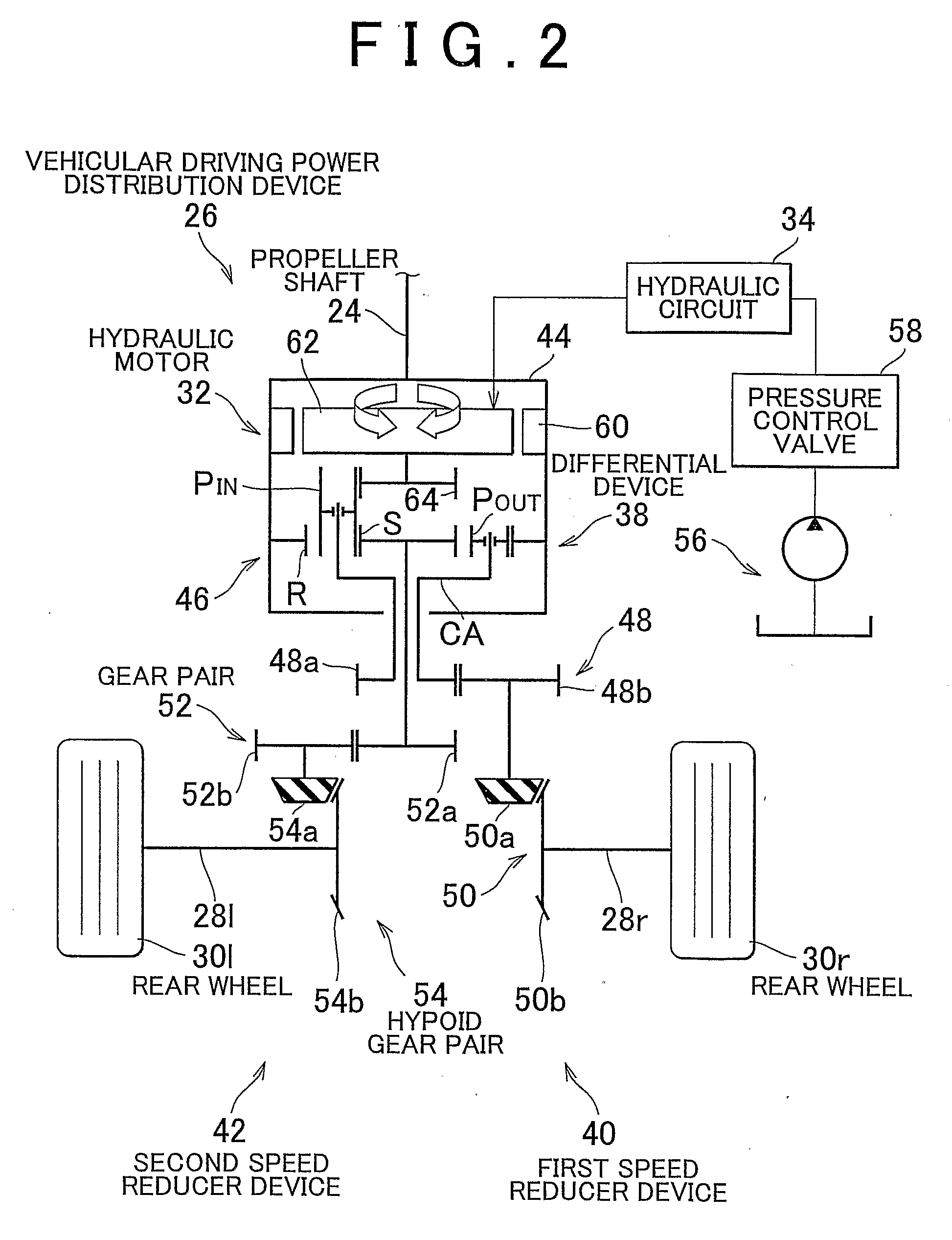
[0042] the driving power distribution device 26 includes: the propeller shaft 24 as a driving power transmission shaft that transmits the driving power generated by the engine 12 as a driving power source and that is disposed so that the axis of rotation thereof is orthogonal to the axis of rotation of each of the right and left rear wheels 30 as driving wheels; the differential device 38 having the planetary gear device 46 that is made up mainly of the first rotating element, the second rotating element and the third rotating element and that is provided concentrically with the axial center of rotation of the propeller shaft 24; and a hydraulic motor 32 fixed to the propeller shaft 24. The first rotating element of the planetary gear device 46 is coupled to the propeller shaft 24, and the second rotating element thereof is connected to the right rear wheel 30r, and the third rotating element is connected to the left rear wheel 30l. The inner pinions PIN of the planetary gear device...

second embodiment

[0051]Subsequently, the invention will be described in detail with reference to the drawings. In the below description, portions common to the embodiments are given the same reference characters, and the description of those portions will be omitted.

[0052]FIG. 4 is a skeleton diagram illustrating a construction of a front-rear-wheel drive vehicle that has a driving power distribution device 66 of a second embodiment of the invention. As shown in FIG. 4, the vehicular driving power distribution device (hereinafter, simply referred to as “driving power distribution device”) 66 of the second embodiment is preferably a device that is suitably applied to the driving power transmission device 10 described above with reference to FIG. 1, or the like. The driving power distribution device 66 includes an electric motor 68 that is driven by electric energy, as an alternative to the above-described hydraulic motor 32 in the driving power distribution device 26.

[0053]FIG. 5 is a skeleton diagra...

third embodiment

[0055]FIG. 6 is a skeleton diagram illustrating a construction of a driving power distribution device of the invention. The driving power distribution device shown in FIG. 6 is provided with a motor for making possible the control of, for example, generating a desired torque difference between the right and left rear wheels 30 or restricting the differential motion therebetween, similarly to the driving power distribution devices 26, 66, and this motor may be either the hydraulic motor 32 or the electric motor 68. In the following description, the motor will be simply referred to as “motor 72”, and the description thereof will be omitted.

[0056]In the driving power distribution device 74 shown in FIG. 6, in place of the output gear 64 coupled to the motor 72 in the construction described above with reference to FIG. 2 and the like, an output gear 76 that is an internal gear and is employed as a torque transfer gear is coupled to the output shaft of the motor 72, and meshes with the i...


PUM


Abstract

A driving power distribution device includes a propeller shaft that transmits the driving power generated by an engine, a differential device having a planetary gear device that is provided concentrically with the axial center of rotation of the propeller shaft, and a hydraulic motor fixed to the propeller shaft. The ring gear of the planetary gear device is coupled to the propeller shaft. The carrier is connected to a right rear wheel. The sun gear is connected to a left rear wheel. Inner pinions of the planetary gear device are driven by the hydraulic motor. Therefore, while the driving power generated by the engine is being distributed to the right and left rear wheels, a control of generating a desired torque difference or restricting the differential motion can be performed. Also, the actuator torque capacity can be reduced, so that size reduction of the device is made possible.

Description

BACKGROUND OF THE INVENTION[0001]1. Field of the Invention[0002]The invention relates to an improvement in a vehicular driving power distribution device that distributes the driving power generated by a driving power source to right and left driving wheels.[0003]2. Description of the Related Art[0004]Vehicular driving power distribution devices that distribute the driving power generated by a driving power source to right and left driving wheels are known. Examples of the devices are driving power distribution control devices described in Japanese Patent Application Laid-Open Publication HEI 7-164852 and Japanese Patent Application Publication JP-A-2001-39179. According to a technology disclosed in Japanese Patent Application Laid-Open Publication HEI 7-164852, by individually controlling the clutching forces of clutches that are provided corresponding to right and left driving wheels, respectively, the driving power can be distributed to the right and left driving wheels at an arbi...

Claims


Application Information

Patent Timeline
IPC IPC(8): B60W10/12F16H48/06B60K17/348F16H48/10F16H48/18F16H48/30F16H48/36
CPCB60K17/10B60K17/35F16H48/10F16H48/11F16H48/20F16H2048/364F16H48/36F16H2048/104F16H2048/106F16H2048/204F16H48/30
Inventor IKUSHIMA, YOSHIHIRO
Owner TOYOTA JIDOSHA KK
Why Eureka
Try Eureka