Heat exchanger and refrigeration cycle apparatus having the same

a technology of heat exchanger and refrigeration cycle, which is applied in the direction of indirect heat exchanger, light and heating apparatus, stationary plate conduit assembly, etc., can solve the problem that the heat exchanger cannot be easily made to have a thin shape, and achieve the effect of minimizing the dead zone, reducing the pressure loss of refrigerant, and improving the heat exchange performan

Inactive Publication Date: 2009-04-02
LG ELECTRONICS INC
View PDF5 Cites 31 Cited by
  • Summary
  • Abstract
  • Description
  • Claims
  • Application Information

AI Technical Summary

Benefits of technology

[0013]Another object of the present invention is to provide a heat exchanger capable of being made thin and that minimizes a dead zone to which air and refrigerant are not transferred to improve the heat transfer performance of the heat exchange.
[0014]Yet another object of the present invention is to provide a refrigeration cycle apparatus having a heat exchanger capable of being made thin and that minimizes the pressure loss of refrigerant.

Problems solved by technology

However, because the diameters of the refrigerant tubes 102 and 104 are equal to each other in the heat exchanger having the above-described structure, the heat exchanger cannot be easily made to have a thin shape.

Method used


Image

  • Heat exchanger and refrigeration cycle apparatus having the same
  • Heat exchanger and refrigeration cycle apparatus having the same
  • Heat exchanger and refrigeration cycle apparatus having the same

Examples


Embodiment Construction

[0027]Hereinafter, embodiments of the present invention will be described in detail with reference to the accompanying drawings.

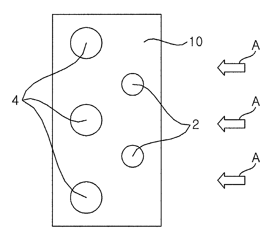
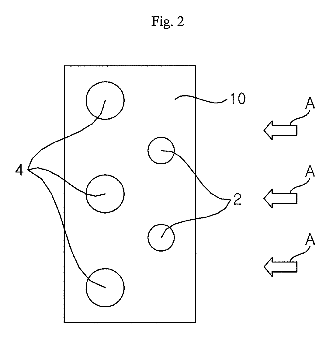
[0028]FIG. 2 is an overview illustrating a heat exchanger according to an embodiment of the present invention. As shown, the heat exchanger includes a plurality of columns of refrigerant tubes 2 and 4 through which refrigerant passes and fins 10 coupling the plurality of columns of refrigerant tubes 2 and 4. Further, the plurality of fins 10 are coupled to the refrigerant tubes 2 and 4 by a predetermined distance.

[0029]In addition, the refrigerant tubes 2 and 4 are longitudinally arranged to be orthogonal to the flowing direction of air A and the fins 10 are arranged to run parallel to the flowing direction of the air A. The refrigerant tubes 2 and 4 also include former columns of refrigerant tubes 2 positioned in the front in the air flowing direction and latter columns of refrigerant tubes 4 positioned in the rear. The former columns of refrigerant tubes ...


PUM


Abstract

A heat exchanger including a plurality of first refrigerant tubes, and a plurality of second refrigerant tubes separated from the plurality of first refrigerant tubes in an air flow direction. Further, a diameter of a respective refrigerant tube of the plurality of first refrigerant tubes is smaller than a diameter of a respective refrigerant tube of the plurality of second refrigerant tubes.

Description

[0001]This nonprovisional application claims priority under 35 U.S.C. § 119(a) on Patent Application No. 10-2007-0088489 filed in the Republic of Korea to Aug. 31, 2007, the entire contents of which are hereby incorporated by reference.BACKGROUND OF THE INVENTION[0002]1. Field of the Invention[0003]The present invention relates to a heat exchanger for exchanging heat between refrigerant and air and a refrigeration cycle apparatus having the same, and more particularly, to a heat exchanger in which a plurality of refrigerant tubes through which refrigerant passes are provided back and forth in an air flowing direction and a refrigeration cycle apparatus having the same.[0004]2. Description of the Background Art[0005]A refrigeration cycle apparatus for cooling / heating the room using a refrigeration cycle generally includes a compressor, a condenser, an expander, and an evaporator. Further, a heat exchanger including the condenser and the evaporator has a refrigerant channel through wh...

Claims


Application Information

Patent Timeline
Patent Type & Authority Applications(United States)
IPC IPC(8): F25B1/00F28D1/04
CPCF25B39/00F25B2500/01F28D1/0477F28D1/05333F28F2215/02F28D2021/0071F28F1/325F28F13/08F28F2210/08F28D2021/007F28D9/00F28F1/00
Inventor KIM, DONG HWISA, YONG CHEOLLEE, HAN CHOONLEE, SANG YEULKIM, JU HYOKKIM, HONG SEONG
Owner LG ELECTRONICS INC
Why Eureka
Try Eureka