
Carbon nanotube MEMS assembly

a technology of carbon nanotubes and mems, which is applied in the direction of generators/motors, transportation and packaging, coatings, etc., can solve the problems of difficult insertion of cnts into other structures, difficulty in manipulating individual cnts, and problematic use of cnts as structural components

Active Publication Date: 2009-04-02
BRIGHAM YOUNG UNIV
View PDF105 Cites 49 Cited by
  • Summary
  • Abstract
  • Description
  • Claims
  • Application Information

AI Technical Summary

Problems solved by technology

While the behavior of CNTs has been widely studied, the use of CNTs as structural components has proved problematic due to a variety of issues, including the difficulty of manipulating individual CNTs, the difficulty of incorporating CNTs into other structures, and the inherently fragile nature CNTs.

Method used


Image

  • Carbon nanotube MEMS assembly
  • Carbon nanotube MEMS assembly
  • Carbon nanotube MEMS assembly

Examples


Embodiment Construction

[0016]The following detailed description of exemplary embodiments of the invention makes reference to the accompanying drawings, which form a part hereof and in which are shown, by way of illustration, exemplary embodiments in which the invention may be practiced. While these exemplary embodiments are described in sufficient detail to enable those skilled in the art to practice the invention, it should be understood that other embodiments may be realized and that various changes to the invention may be made without departing from the spirit and scope of the present invention.

[0017]In describing and claiming the present invention, the following terminology will be used.

[0018]As used here, the term “vertically grown” is used to describe nanotubes that are generally grown upward from a substrate or catalyst material. While such nanotubes exhibit a generally vertical attitude, it is to be understood that such tubes are not necessarily perfectly straight or perfectly upright, but will te...


PUM


Abstract

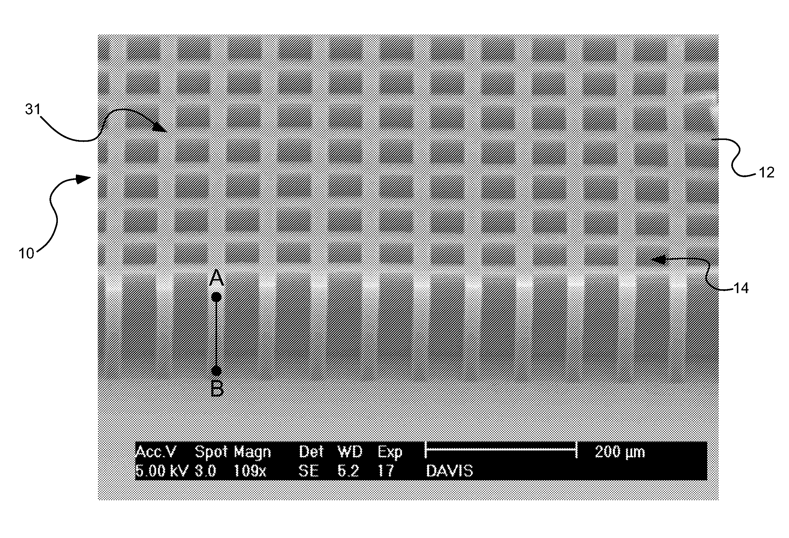
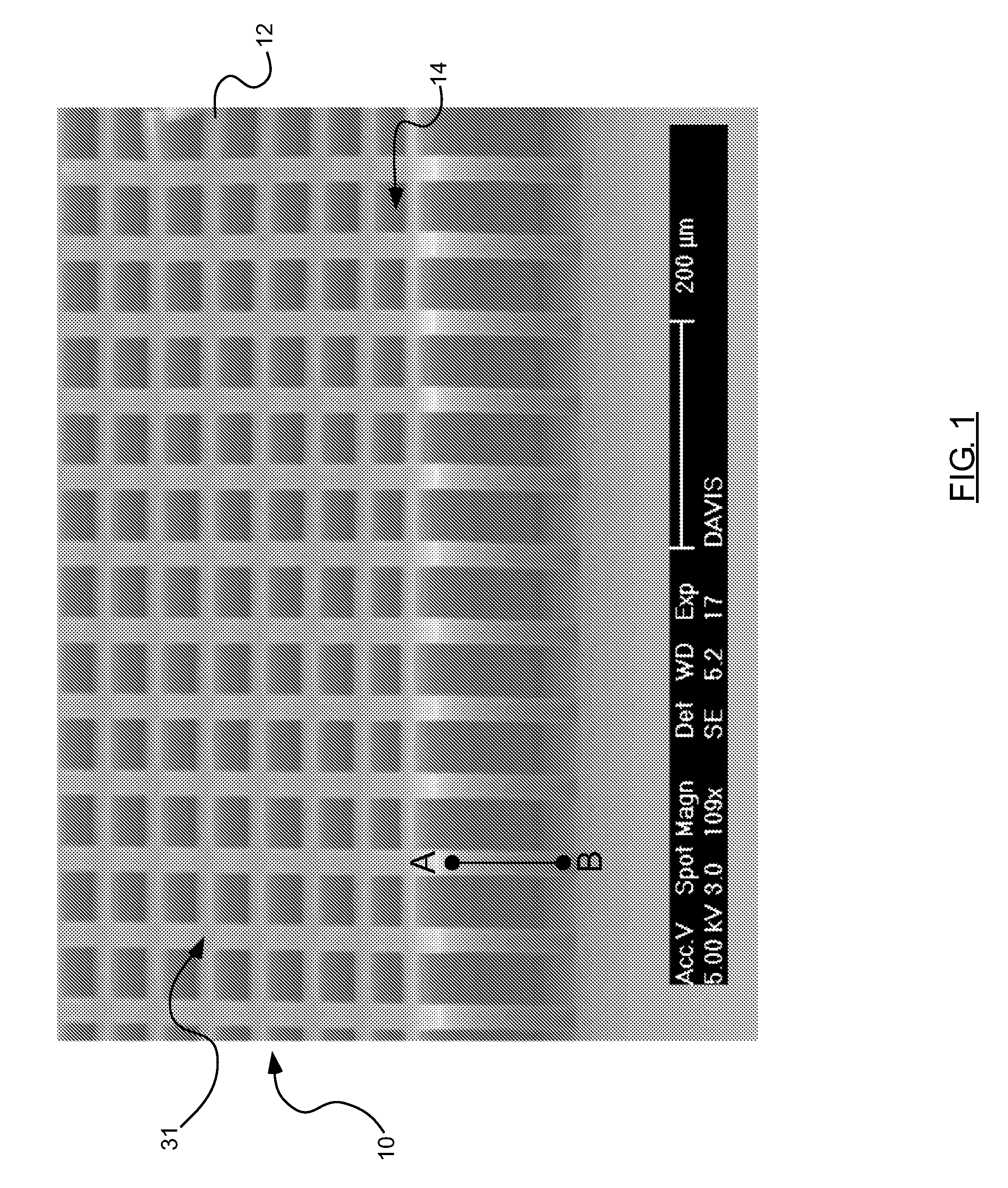
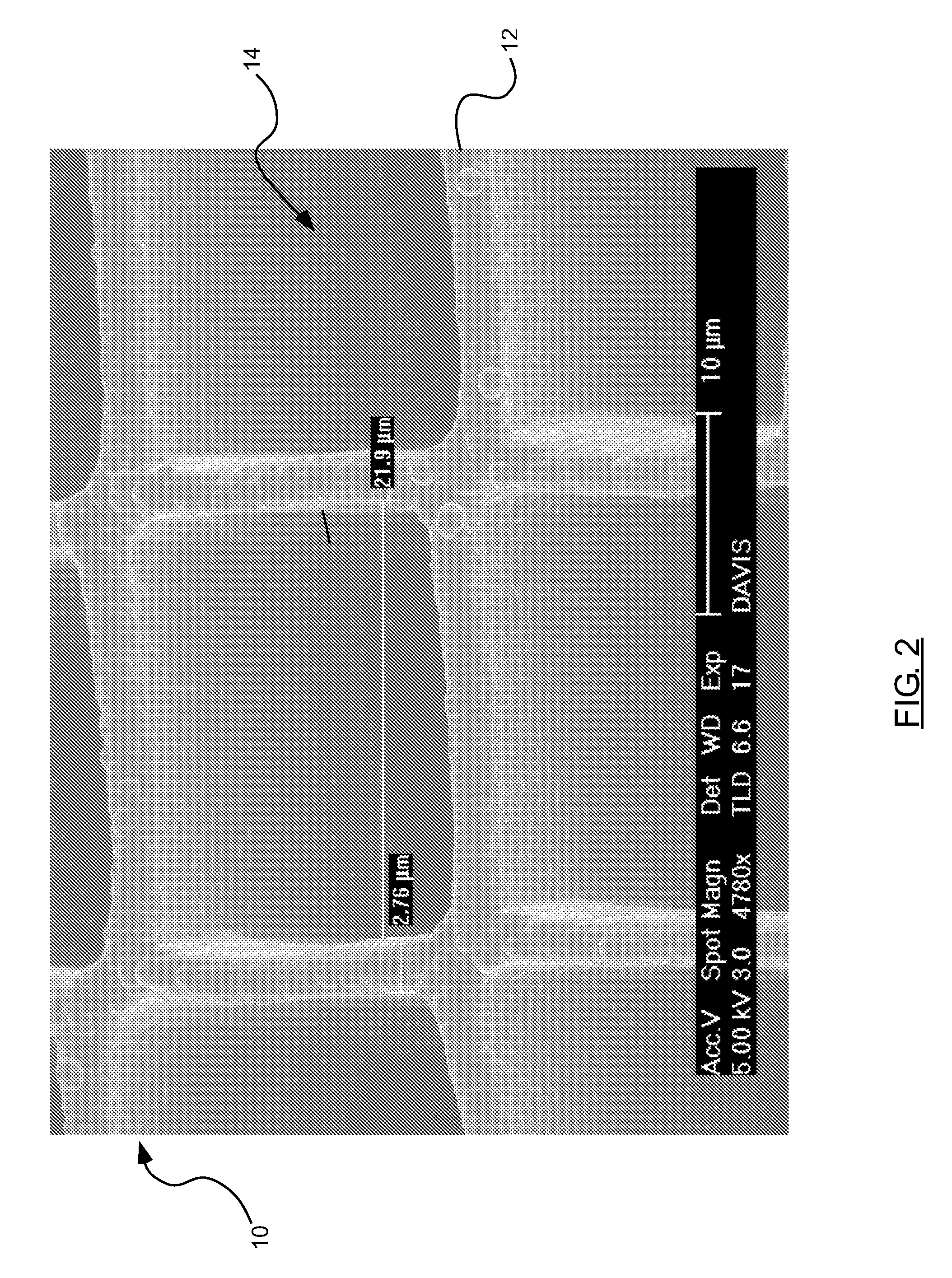
A carbon nanotube MEMS assembly comprises a plurality of carbon nanotubes oriented into a patterned frame, the patterned frame defining at least two components of a MEMS device. An interstitial material at least partially binds adjacent carbon nanotubes one to another. At least one component of the frame is fixed and at least one component of the frame is movable relative to the fixed component.

Description

PRIORITY[0001]Priority is claimed of U.S. Provisional Patent Application Ser. No. 60 / 995,881, filed Sep. 28, 2007, which is hereby incorporated herein by reference in its entirety.RELATED APPLICATIONS[0002]This application is related to U.S. patent application Ser. No. ______, filed Sep. 26, 2008, entitled Carbon Nanotube Assembly; and is related to U.S. patent application Ser. No. ______, filed Sep. 26, 2008, entitled X-Ray Radiation Window with Carbon Nanotube Frame.BACKGROUND[0003]Interest in the use of carbon nanotubes (“CNTs”) in engineering applications continues to increase. CNTs are tubes of graphite typically grown from iron nanoparticles or iron, and can be categorized as single-walled nano-tubes (“SWNTs”) or multi-walled nanotubes(“MWNTs”). CNTs have many interesting properties, including exhibiting the highest tensile strength and elastic modulus of any known material.[0004]While the behavior of CNTs has been widely studied, the use of CNTs as structural components has p...

Claims


Application Information

Patent Timeline
Patent Type & Authority Applications(United States)
IPC IPC(8): H02N1/00
CPCC01B2202/34C01B2202/36B81C1/00031C01B31/0226B82Y30/00B82Y40/00Y10T428/24273H01J5/18B81B2201/018C01B2202/20B81B2203/0109C01B31/0253C01B32/16C01B32/168
Inventor DAVIS, ROBERT C.VANFLEET, RICHARD R.HUTCHISON, DAVID N.
Owner BRIGHAM YOUNG UNIV
Learn More