Eureka AIR delivers breakthrough ideas for toughest innovation challenges, trusted by R&D personnel around the world.

Stabilizing mechanism for a deployed reflector antenna in a mobile satellite antenna system and method

Inactive Publication Date: 2009-04-02
WINEGARD
View PDF17 Cites 11 Cited by
  • Summary
  • Abstract
  • Description
  • Claims
  • Application Information

AI Technical Summary

Benefits of technology

[0006]A stabilizing mechanism and method for a deployed reflector antenna in a mobile satellite system substantially minimizes deflection during adverse environmental forces.
[0008]A method of stabilizing a reflector antenna in a mobile satellite antenna system applies a force against opposing sides on the rear of the reflector antenna as the reflector antenna is deployed in the satellite mobile system. The applied force increases as the reflector antenna deploys. When the reflector is fully deployed, the force applied is the greatest to minimize deflection of the reflector antenna in the presence of environmental forces.

Problems solved by technology

These systems need to be rugged and reliable and are often subject to use in severe weather environments.
Such large reflectors when deployed may be subject to severe weather that can deflect the satellite antenna off the target satellite resulting in communication loss.

Method used


Image

  • Stabilizing mechanism for a deployed reflector antenna in a mobile satellite antenna system and method
  • Stabilizing mechanism for a deployed reflector antenna in a mobile satellite antenna system and method
  • Stabilizing mechanism for a deployed reflector antenna in a mobile satellite antenna system and method

Examples


Embodiment Construction

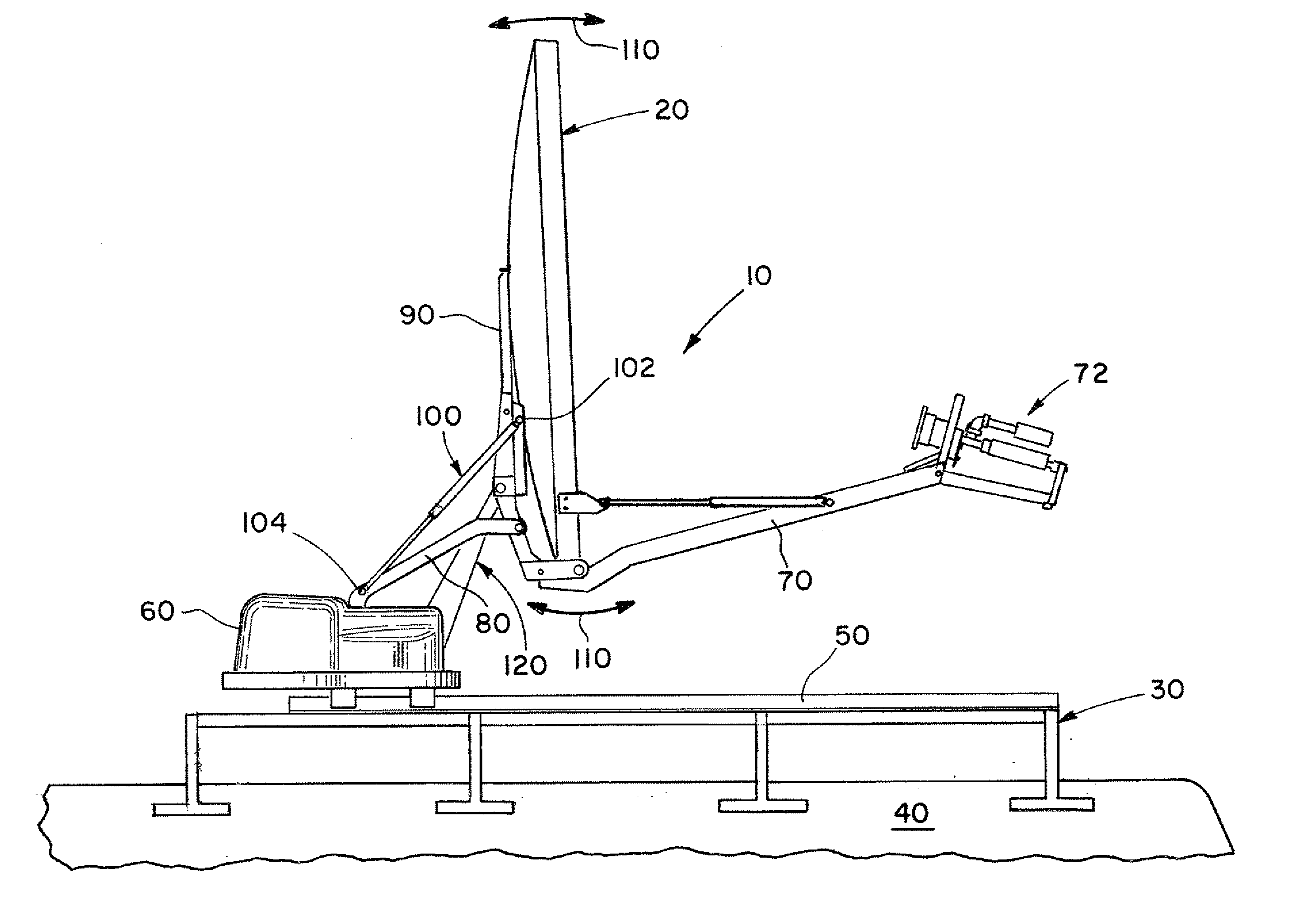
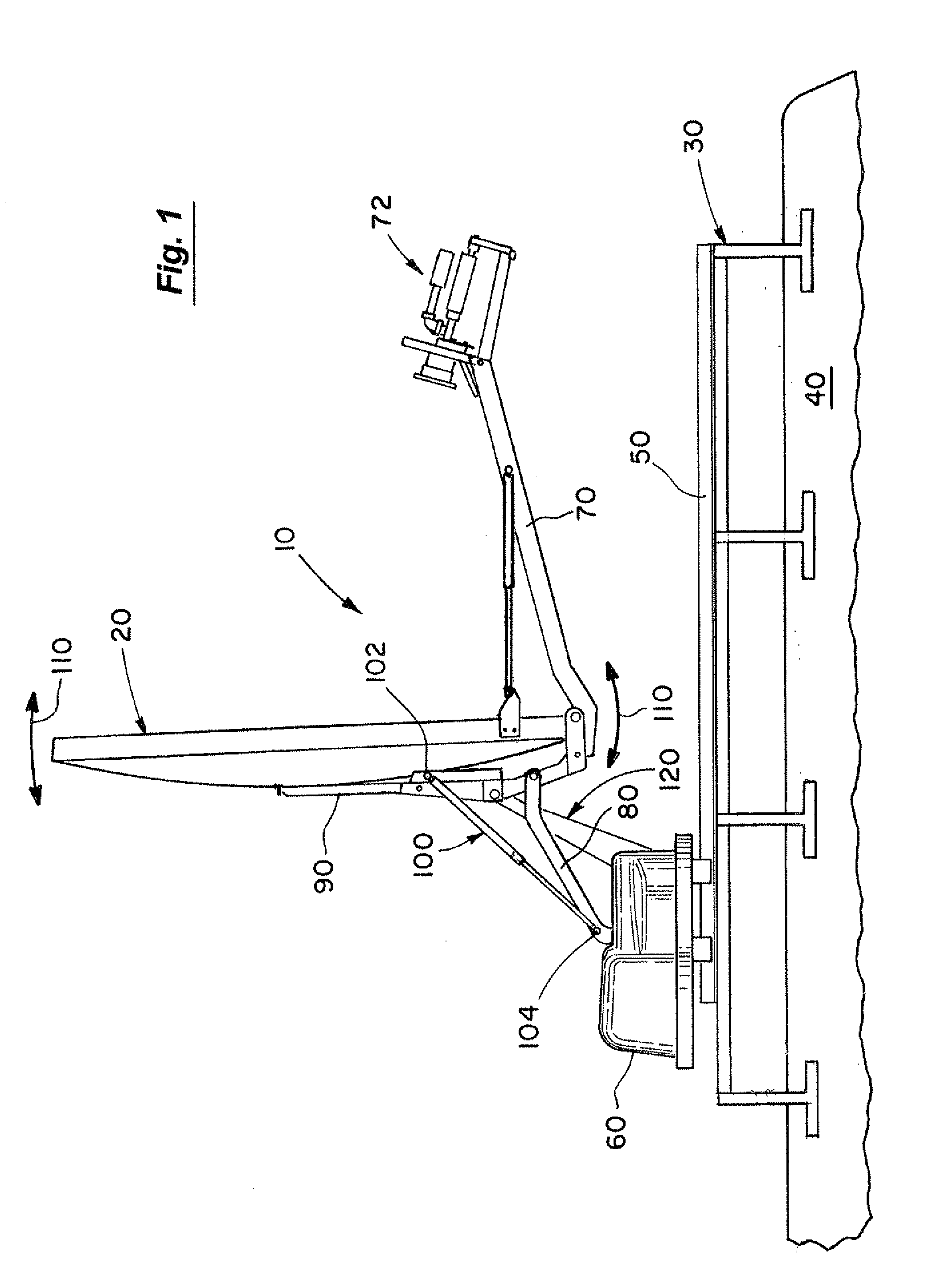
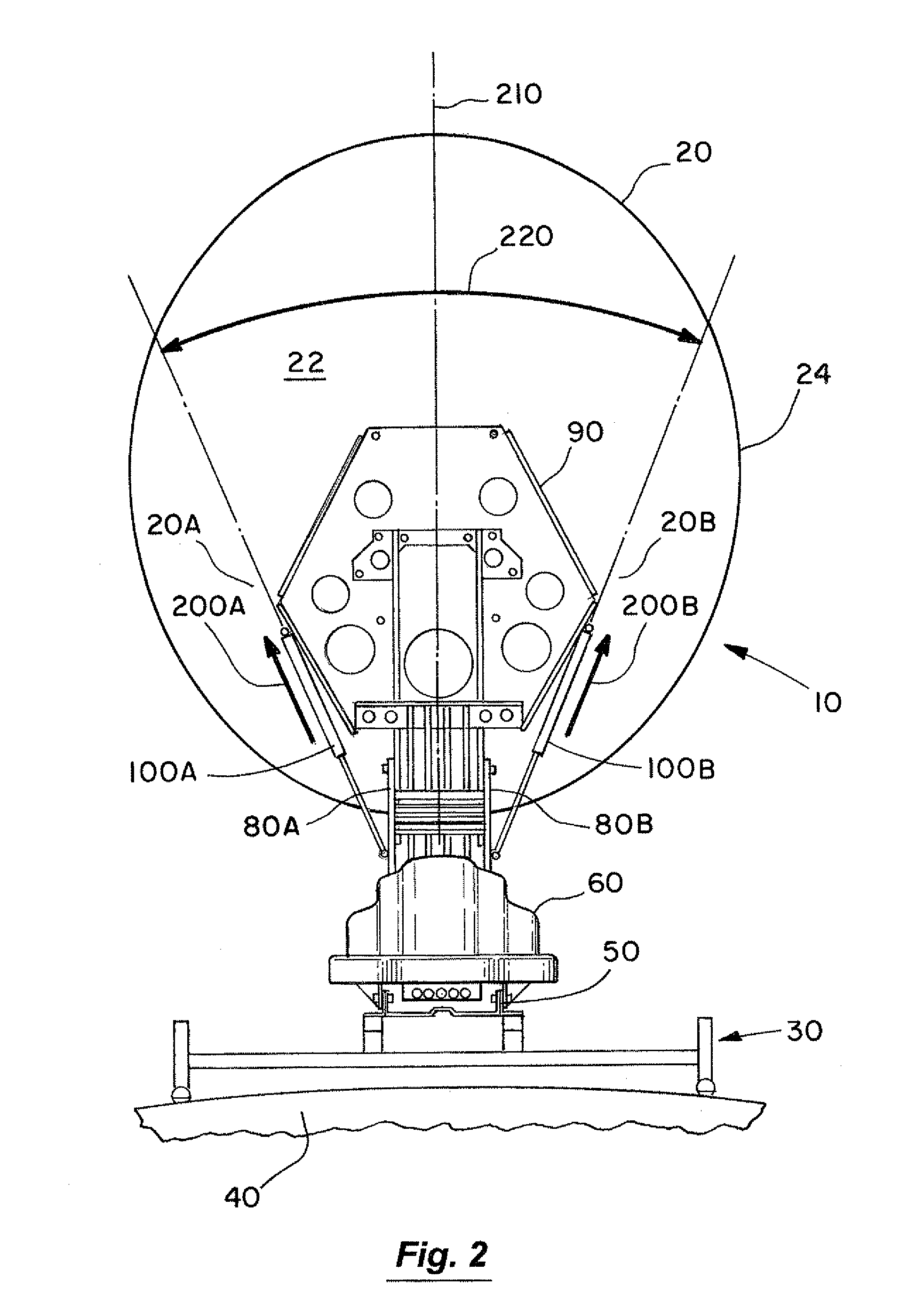
[0016]In FIG. 1, the mobile satellite system 10 of the present invention is shown, with the reflector antenna 20 moving (as shown by arrows 110) between a deployed position and a stowed position. The mobile satellite system 10 is shown mounted on support 30 of a vehicle 40. The mobile satellite system 10 of FIGS. 1 through 4 has a track 50, a housing 60 containing motors, gears, controls (not shown), and a feed support arm 70 carrying a feed 72. A tilt mechanism 80 (such as tilt links 80A, 80B) tilts the reflector antenna 20 as it is lifted by a lift mechanism 120 to deploy. The tilt mechanism 80 is part of the lift mechanism 120. The mobile satellite system 10 of the present invention is of the type found in U.S. Pat. No. 7,230,581 and incorporated herein by reference. The details of the support 30, the housing 60, the track 10, the feed arm 70 and the feed 72 are not necessary to practice the teachings of the various embodiments of the present invention. Nor, is the present invent...


PUM


Abstract

A stabilizing mechanism and method for a deployed reflector antenna in a mobile satellite system. The stabilizing mechanism has a pair of stabilizing devices with a first end of each stabilizing device connected on a rear support of the reflector antenna. The first ends are positioned on opposite sides of the rear support. A second end of each stabilizing device is connected to a tilt mechanism in the mobile satellite system. The pair of stabilizing devices forms a support angle about the centerline of the reflector antenna and with the tilt mechanism. The pair of stabilizer devices pushes against the opposite sides with a pre-load force when the reflector antenna is deployed to minimize deflection of the reflector antenna due to environmental forces.

Description

BACKGROUND OF THE INVENTION[0001]1. Field of the Invention[0002]The invention relates to the field of mobile satellite antenna systems and, more particularly, to mechanisms and methods stabilizing deployed reflector antennas in mobile satellite systems during use to maintain communication with a target satellite under adverse environmental conditions.[0003]2. Discussion of the Background[0004]Mobile satellite systems, mounted on a wide variety of vehicles, are used worldwide to provide two-way satellite communications such as, for example, broadband data, video conferencing and other corporate communications for diverse uses as found in oil and gas, construction, military, mobile education, emergency medical and service providers, and news organizations. These systems need to be rugged and reliable and are often subject to use in severe weather environments. A mobile satellite system deploys a reflector antenna and automatically targets it on a satellite in orbit at a desired locati...

Claims


Application Information

Patent Timeline
IPC IPC(8): H01Q3/02H01Q1/08
CPCH01Q1/08H01Q19/13H01Q1/3275H01Q1/3216
Inventor CONRAD, TIMOTHY JOHN
Owner WINEGARD
Why Eureka
Eureka Blog
Learn More