Higher pressure, modular target system for radioisotope production

a radioisotope and target system technology, applied in the field of radioisotope production methods and systems, can solve the problems of sustaining heat damage and window energy loss, and still absorbing some beam energy

Inactive Publication Date: 2009-04-09
ADVANCED APPLIED PHYSICS SOLUTIONS
View PDF7 Cites 30 Cited by
  • Summary
  • Abstract
  • Description
  • Claims
  • Application Information

AI Technical Summary

Benefits of technology

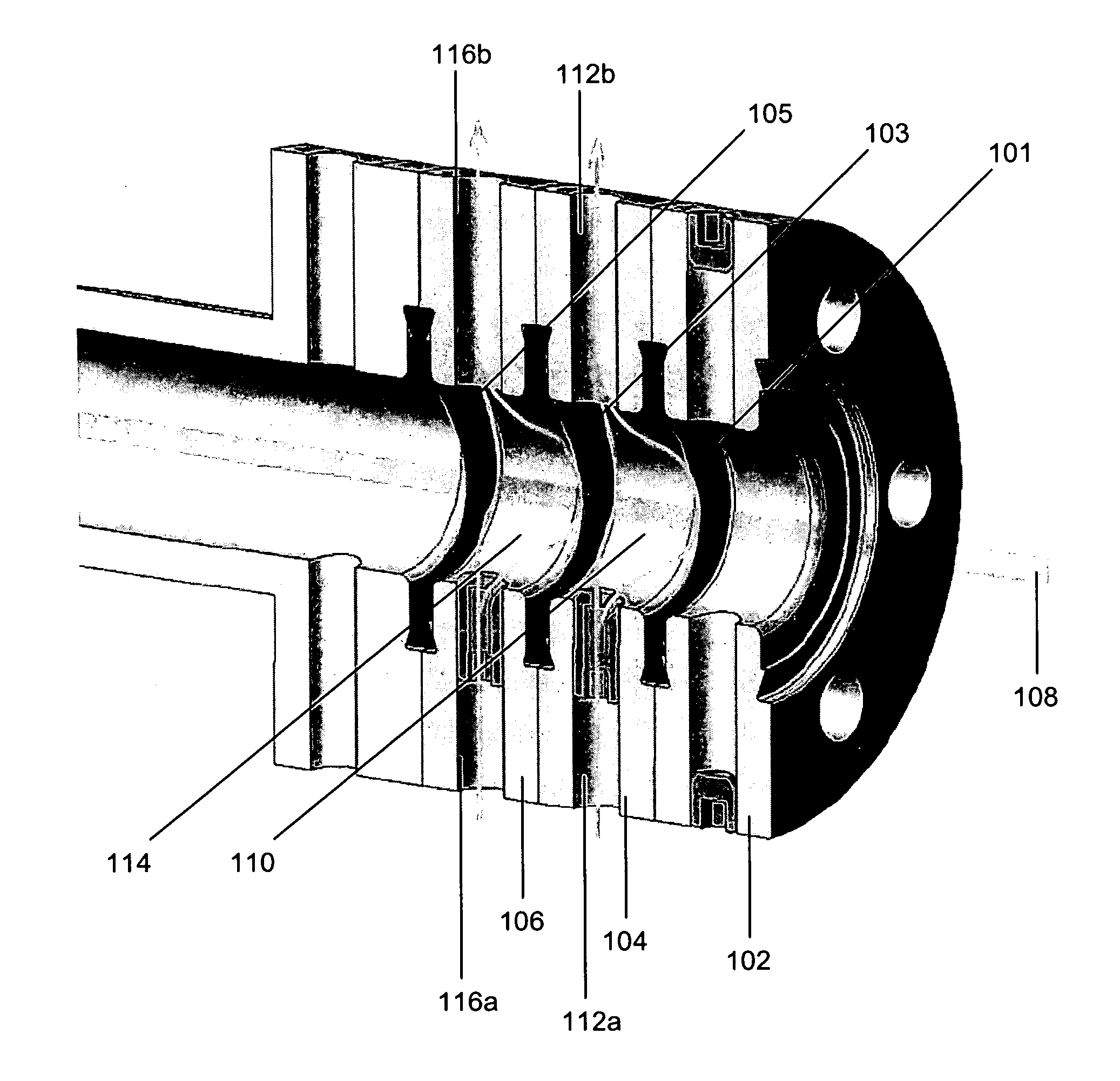
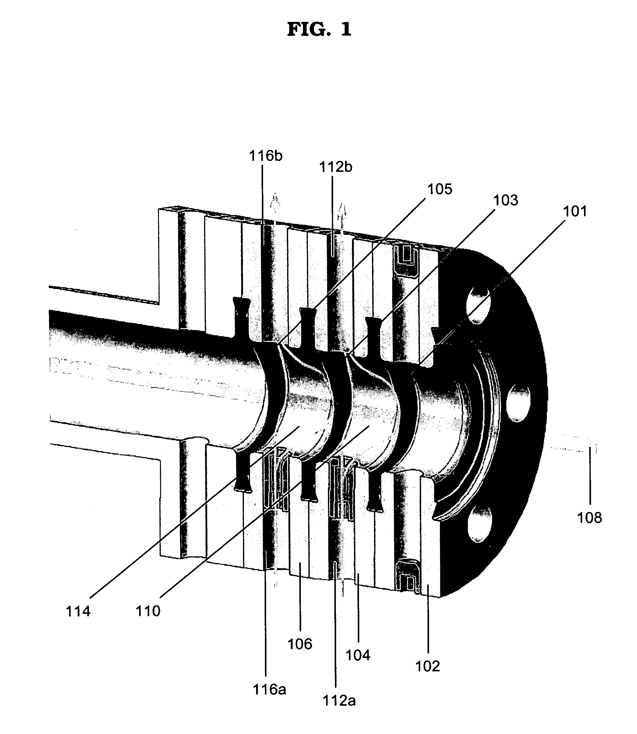
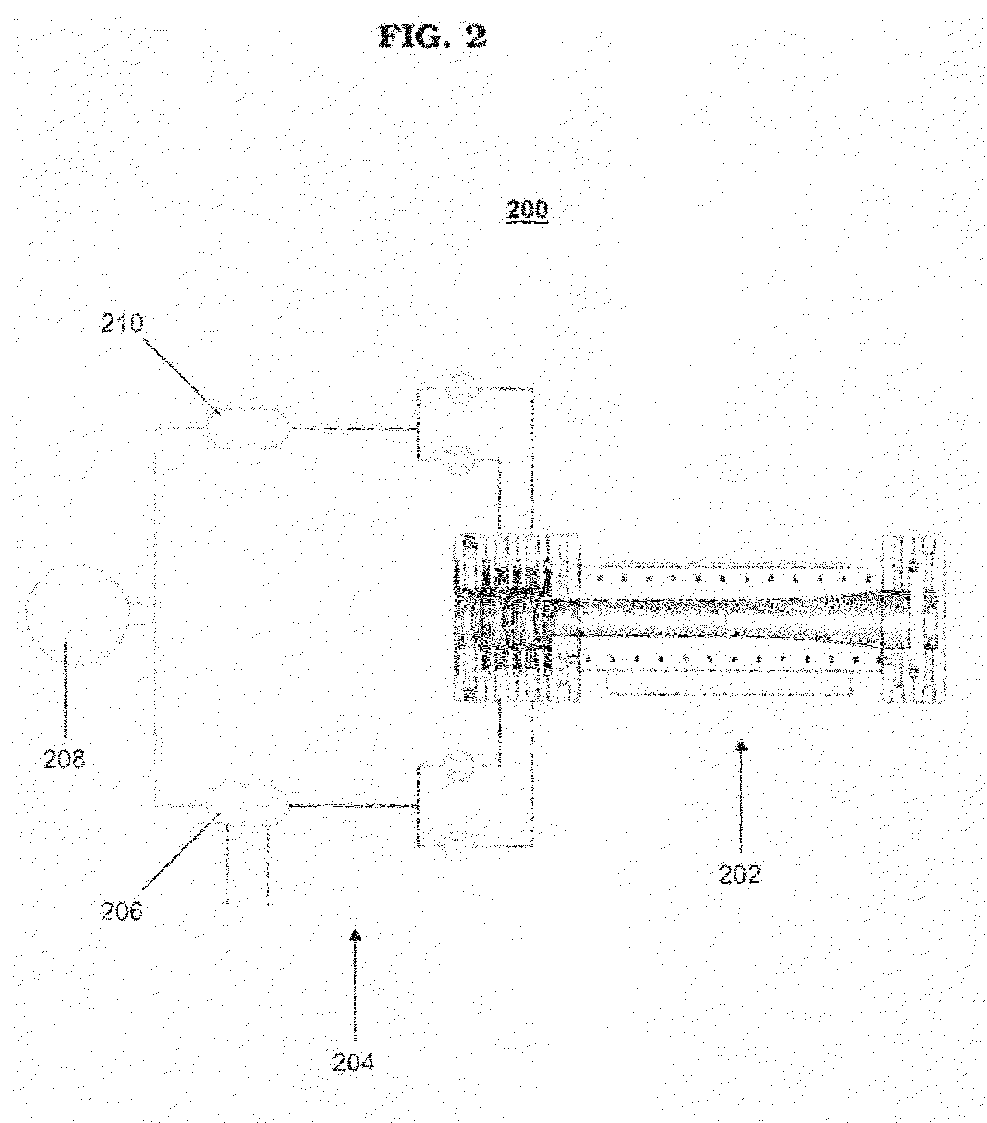
[0008]A target system according to example embodiments may include a target assembly having a beam stop, a target chamber, and at least one window module. The target chamber may have a length of about 120-250 mm. The target assembly may include a plurality of window modules. For example, two window modules may be incorporated in the target assembly so as to define a coolant channel there between. A pressure in the coolant channel may be less than a pressure in the target chamber. The target system may also include a cooling unit configured to supply a liquid coolant to the coolant channel. The coolant may be liquid helium. The target system may further include a collimator for shaping an irradiating beam.

Problems solved by technology

Although relatively transparent to an irradiating beam (particularly at higher beam currents), a beam window will nevertheless still absorb some of the beam energy and can sustain heat damage if not properly cooled.

Method used


Image

  • Higher pressure, modular target system for radioisotope production
  • Higher pressure, modular target system for radioisotope production
  • Higher pressure, modular target system for radioisotope production

Examples


Embodiment Construction

[0019]It will be understood that when an element or layer is referred to as being “on”, “connected to”, “coupled to”, or “covering” another element or layer, it may be directly on, connected to, coupled to, or covering the other element or layer or intervening elements or layers may be present. In contrast, when an element is referred to as being “directly on,”“directly connected to,” or “directly coupled to” another element or layer, there are no intervening elements or layers present. Like numbers refer to like elements throughout the specification. As used herein, the term “and / or” includes any and all combinations of one or more of the associated listed items.

[0020]It will be understood that, although the terms first, second, third, etc. may be used herein to describe various elements, components, regions, layers, and / or sections, these elements, components, regions, layers, and / or sections should not be limited by these terms. These terms are only used to distinguish one elemen...


PUM


Abstract

A beam window according to example embodiments may include a foil having an interior region and an exterior region. The interior region of the foil may be dome-shaped, and a central portion of the dome-shaped interior region may be thinner than the exterior region of the foil. The beam window may be welded to a flange to form a window module. One or more window modules may be utilized in a target assembly. The target assembly may further include a cooling unit and/or collimator to form a target system according to example embodiments.

Description

PRIORITY STATEMENT[0001]This application claims the benefit under 35 U.S.C. § 119(e) to U.S. Provisional Application No. 60 / 945,586, filed on Jun. 22, 2007 in the United States Patent and Trademark Office (USPTO), the entire contents of which are incorporated herein by reference.BACKGROUND[0002]1. Technical Field[0003]Example embodiments according to the present application relate to a method and system for radioisotope production.[0004]2. Description of the Related Art[0005]Radioisotopes are conventionally produced by the irradiation of a source material (e.g., source gas) in a target assembly, wherein the target assembly is designed as a dedicated and self-contained unit. This irradiation production method requires the vessel containing the gas to be separated from the accelerator vacuum by a thin barrier (usually known as a “window” or “beam window”). The beam window is relatively transparent to the irradiating beam.[0006]Thin metallic foils are widely used as beam windows. Altho...

Claims


Application Information

Patent Timeline
Patent Type & Authority Applications(United States)
IPC IPC(8): G21G1/00H01J35/18H01J35/12
CPCG21G1/04G21K1/10H05H6/00G21K5/08G21K1/14
Inventor GELBART, WILLIAM Z.PAVAN, ROBERTO A.ZEISLER, STEFAN K.
Owner ADVANCED APPLIED PHYSICS SOLUTIONS
Why Eureka
Try Eureka