
X-ray imaging apparatus

a technology of x-ray imaging and x-ray, which is applied in the direction of instruments, patient positioning for diagnostics, applications, etc., can solve the problems of reducing the operability of the x-ray imaging apparatus, generating an effective image for diagnostics, and unable to obtain proper images, so as to reduce the operability of the vertical position setting, reduce safety, and generate effective images

Inactive Publication Date: 2009-04-09
CANON KK
View PDF6 Cites 5 Cited by
  • Summary
  • Abstract
  • Description
  • Claims
  • Application Information

AI Technical Summary

Benefits of technology

[0018]The present invention is directed to an X-ray imaging apparatus which is capable of taking a general still image as well as a CT image, and which is useful in generating an effective image for diagnostics without reducing operability of the vertical position setting of the X-ray imaging unit and, further, without reducing safety.

Problems solved by technology

However, since radiation detectors of the aforementioned imaging apparatuses are large-sized two-dimensional plane sensors, these imaging apparatuses are generally expensive.
As a result, ease of operability of the X-ray imaging apparatus is reduced.
A similar problem occurs when the image taking mode is changed.
Thus, if an imaging apparatus including a height-adjustable X-ray imaging unit moves the X-ray imaging unit up and down during the CT imaging, proper images may not be obtained and therefore reconstruction becomes difficult.
Since the conventional apparatus does not include a method for prohibiting the up-and-down movement during the rotation, there is a possibility that the X-ray imaging unit moves up-and-down during the image taking.

Method used


Image

  • X-ray imaging apparatus
  • X-ray imaging apparatus
  • X-ray imaging apparatus

Examples


Embodiment Construction

[0027]Various exemplary embodiments, features, and aspects of the invention will now be described in detail with reference to the drawings.

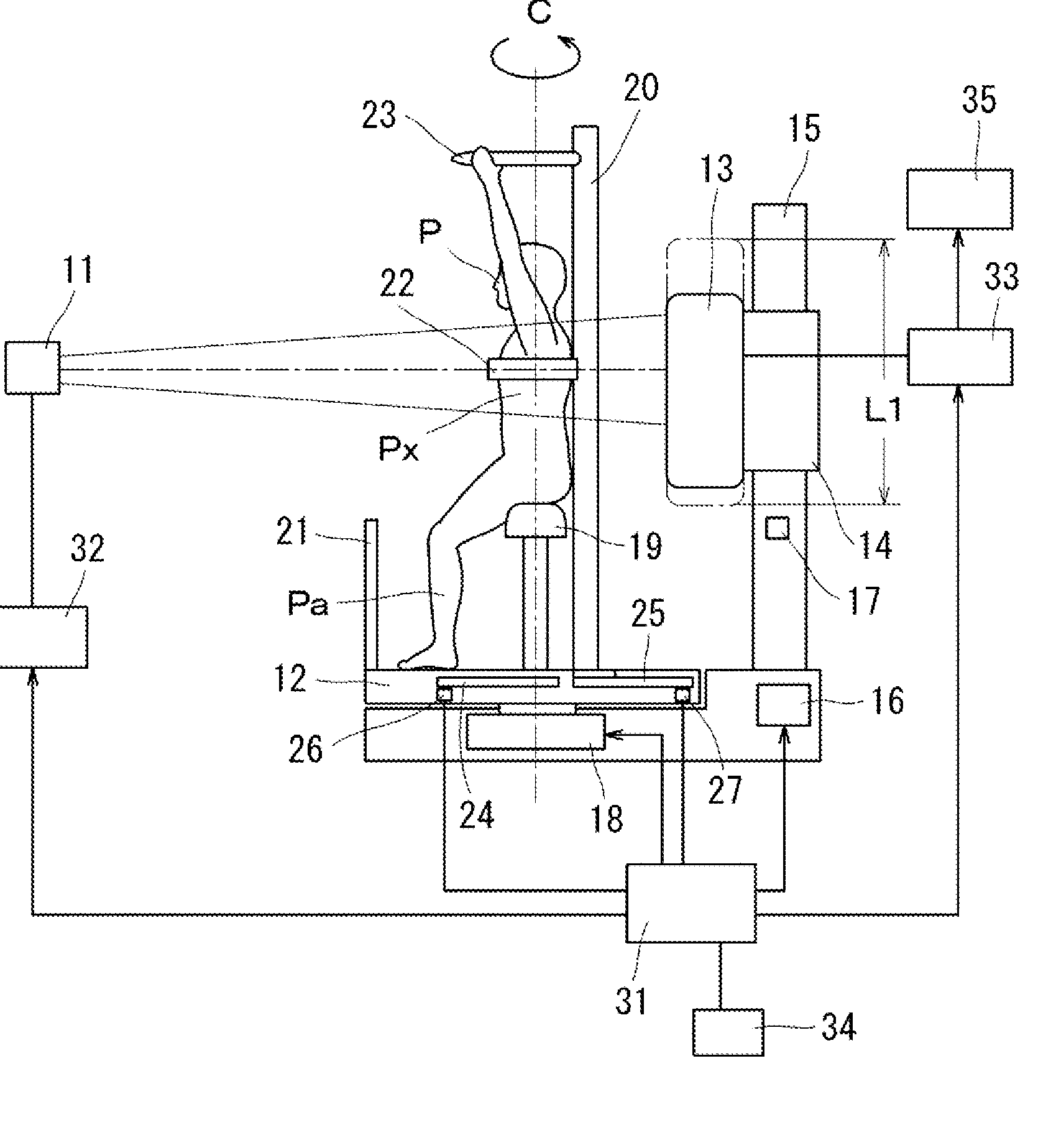
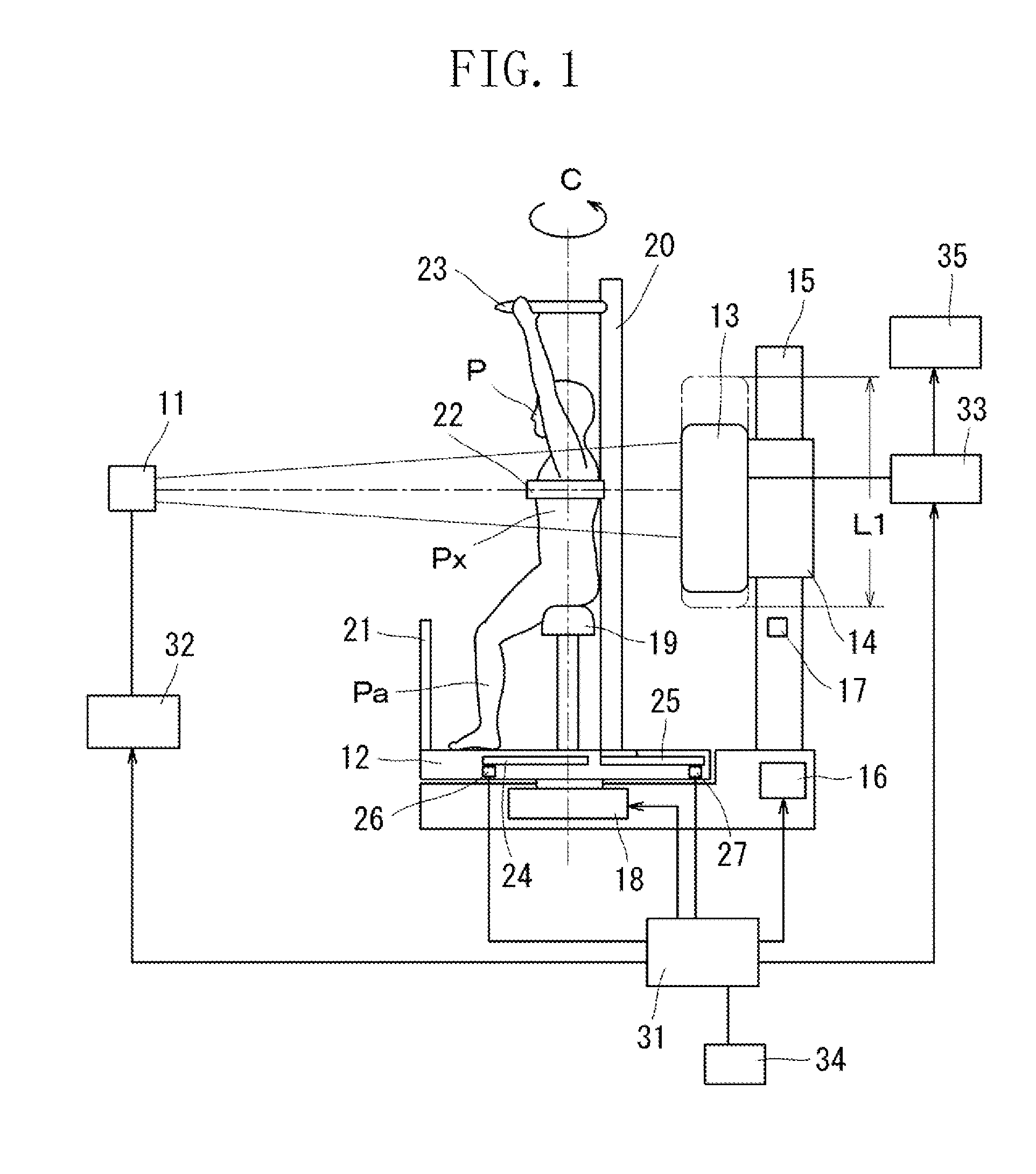
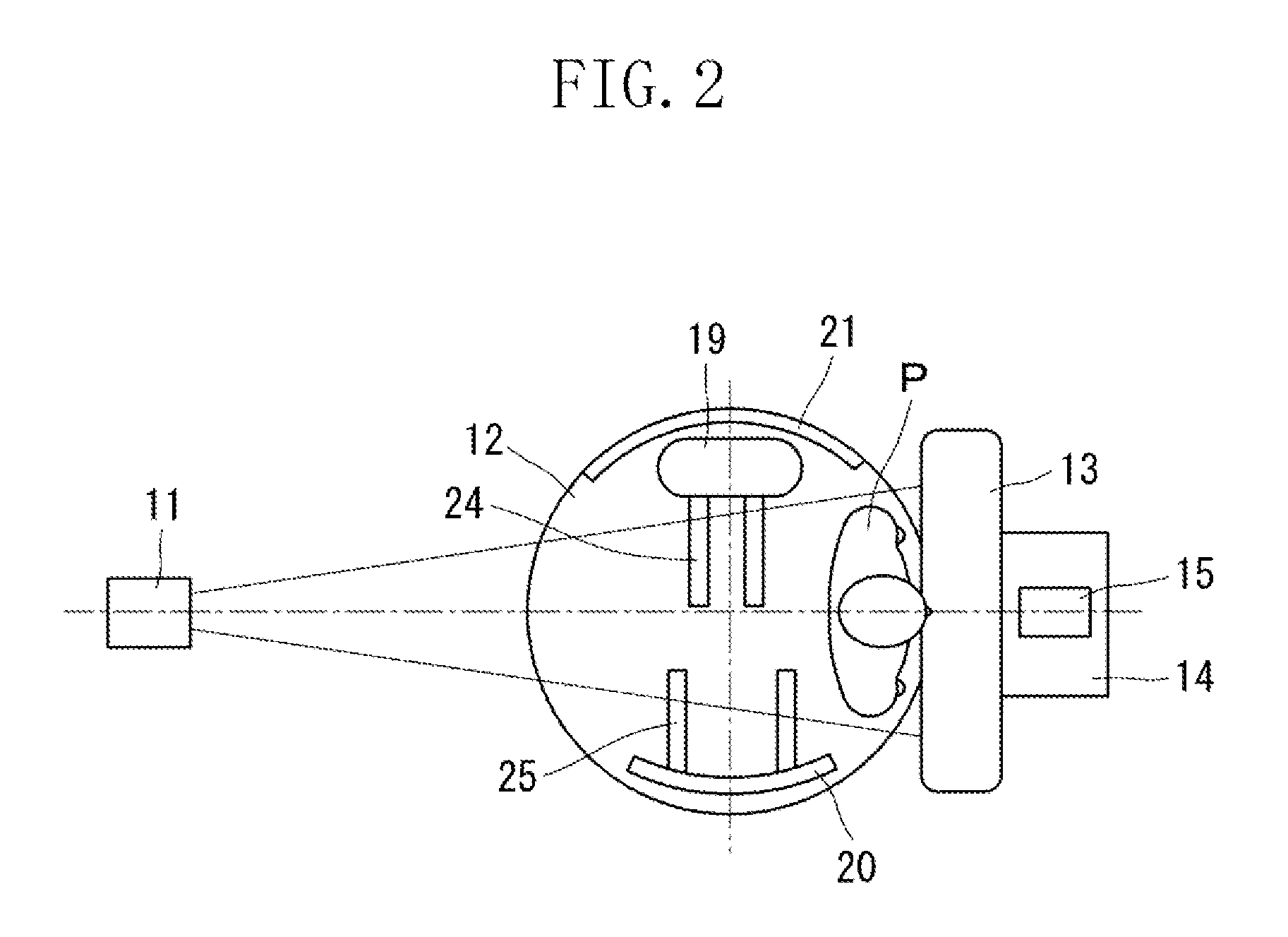
[0028]FIG. 1 illustrates a configuration of an X-ray imaging apparatus in a CT imaging mode in which the subject (P) is rotated during image taking according to an exemplary embodiment of the present invention. In front of an X-ray tube 11, an X-ray imaging unit 13 which is, for example, a plane sensor, is arranged facing the X-ray tube 11. A subject P on a rotating table 12 is positioned between the X-ray tube 11 and the X-ray imaging unit 13. The rotating table 12 is rotatable 360 degrees. The X-ray imaging unit 13 is moveably attached to a column 15 through a slide unit 14. The slide unit 14 is driven up-and-down by an up-and-down drive unit 16. The lowest position of the X-ray imaging unit 13 can be detected by an image taking unit position detector 17.

[0029]The rotating table 12 is supported by a rotary drive unit 18. A chair 19 on which the...


PUM


Abstract

An X-ray imaging apparatus includes an X-ray imaging unit, rotating unit configured to rotate a subject about an axis of rotation relative to the X-ray imaging unit, supporting unit configured to support the subject, and a limiting unit configured to limit the range in which the X-ray imaging unit is moveable along the axis of rotation depending on the position of the supporting means relative to the axis of rotation.

Description

BACKGROUND OF THE INVENTION[0001]1. Field of the Invention[0002]The present invention relates to an X-ray imaging apparatus configured to generate an X-ray image of a subject using an X-ray beam passing through the subject.[0003]2. Description of the Related Art[0004]Conventionally, a computed tomography (CT) apparatus for generating a three-dimensional cross-sectional image of a subject is used in the medical area. In order to obtain the three-dimensional cross-sectional image, radiation emitted to the subject from a circumference of the subject is detected and converted into an image signal after it passes through the subject. Then, through reconstruction processing, the image signal is converted into a three-dimensional cross-sectional image.[0005]A helical scanning CT apparatus is a type of apparatus which is commonly used today. The helical scanning CT apparatus is configured such that a radiation source and a radiation detector, configured as a pair, rotate helically around th...

Claims


Application Information

Patent Timeline
Patent Type & Authority Applications(United States)
IPC IPC(8): A61B6/04A61B6/00
CPCA61B6/4482A61B6/102
Inventor KOBAYASHI, MASAAKI
Owner CANON KK
Features
  • Generate Ideas
  • Intellectual Property
  • Life Sciences
  • Materials
  • Tech Scout
  • Unparalleled Data Quality
  • Higher Quality Content
  • 60% Fewer Hallucinations
Learn More