Wireless remote control device, bridge device and wireless remote control system

a wireless remote control and bridge technology, applied in transmission systems, instruments, television systems, etc., can solve the problems of remote control not being achieved, difficult for one infrared-receiving section to receive an operational signal without fail, and more difficult to achieve operational-information transmission, etc., to achieve the effect of easy wireless transmission of operational information and higher degree of accuracy

Inactive Publication Date: 2009-04-09
SHARP KK
View PDF1 Cites 27 Cited by
  • Summary
  • Abstract
  • Description
  • Claims
  • Application Information

AI Technical Summary

Benefits of technology

[0009]An object of the present invention is to provide a remote control device that remotely controls an electronic device such as audio-visual equipment and easily allows wireless transmission of

Problems solved by technology

With the remote control device mentioned above, however, since infrared rays have a higher degree of linear propagation than other radio waves, when there is an obstruction between the remote control device and an infrared-receiving section in an electronic device, it is highly likely that the electronic device is prevented from being remotely controlled.
In a case where a television broadcast receiver is remotely controlled, when, for example, a user attempts to operate it by directing a remote control device toward the middle of its screen, it may be difficult for one infrared-receiving section

Method used


Image

  • Wireless remote control device, bridge device and wireless remote control system
  • Wireless remote control device, bridge device and wireless remote control system
  • Wireless remote control device, bridge device and wireless remote control system

Examples


first embodiment

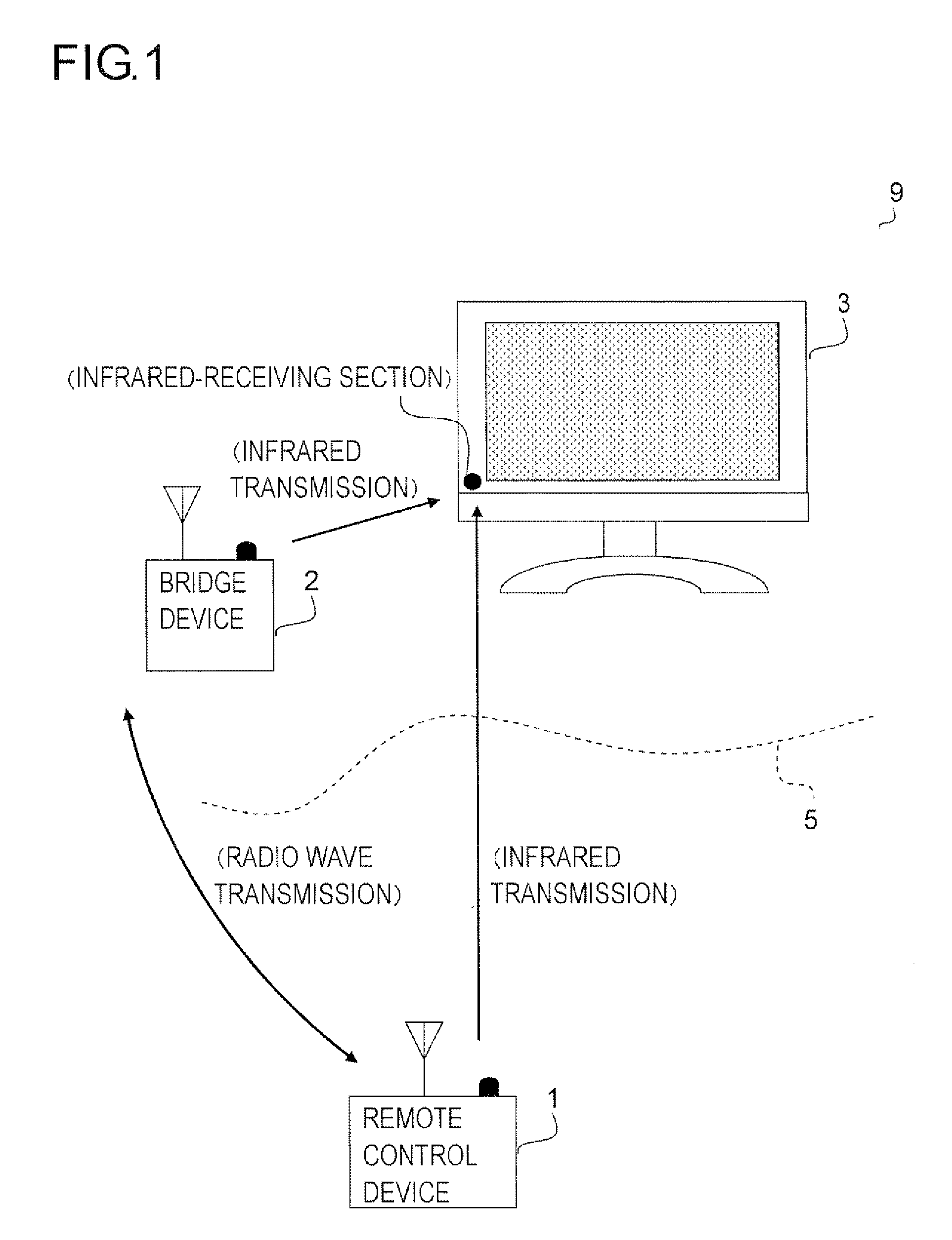
[0039]A television broadcast receiving system will be described below as the first embodiment of the invention. The configuration of the television broadcast receiving system is schematically shown in FIG. 1. As shown in the figure, the television broadcast receiving system 9 has a remote control device 1, a bridge device 2 and a television broadcast receiver 3.

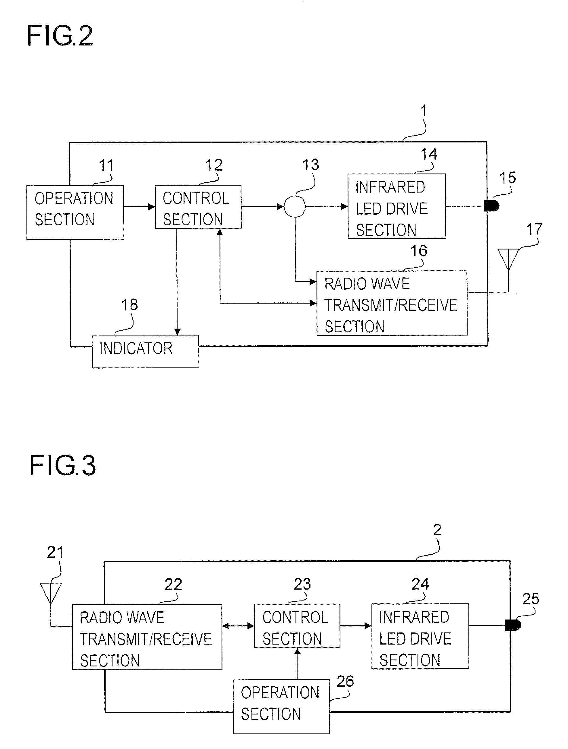
[0040]The remote control device 1 includes, as shown in FIG. 2, an operation section 11, a control section 12, a switch 13, an infrared LED drive section 14, an infrared LED 15, a radio wave transmit / receive section 16, an antenna 17 and an indicator 18.

[0041]The operation section 11 is configured to serve as a user interface provided with push-button switches and other controls. A signal (an operational signal) corresponding to an operation performed here is fed to the control section 12. Thus, a user can enter operational information (for example, information on operations such as the turning on and off of power and the swi...

second embodiment

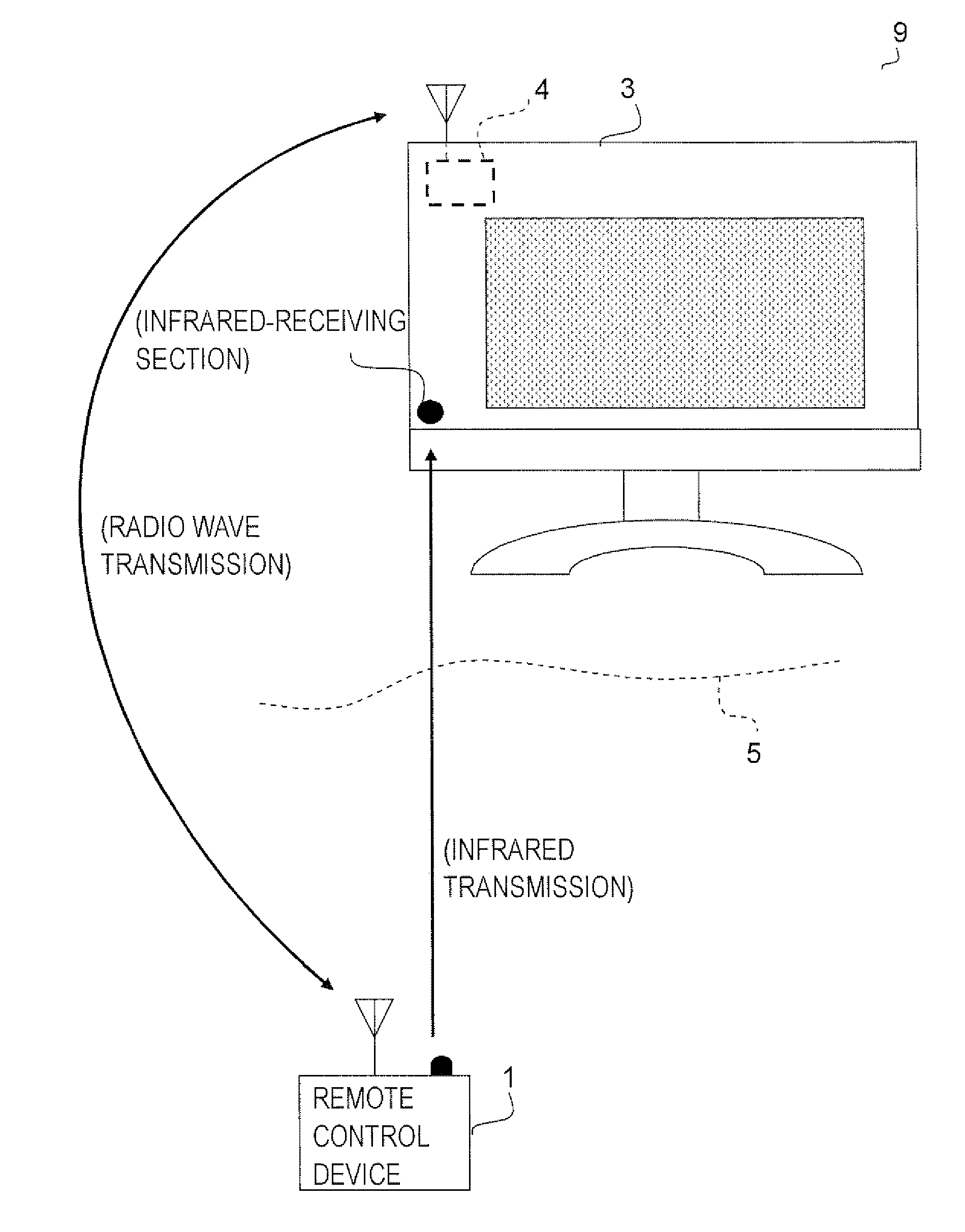
[0072]Likewise, a television broadcast receiving system will be described below as the second embodiment of the invention. The configuration of the television broadcast receiving system is schematically shown in FIG. 5. As shown in the figure, the television broadcast receiving system 9 has a remote control device 1 and a television broadcast receiver 3. In this embodiment, since the configuration of the remote control device 1, the details of operational information and the like are the same as those in the first embodiment, their description will not be repeated.

[0073]A bridge device 4 of this embodiment is incorporated into the television broadcast receiver 3 as a component (module) thereof. The configuration of the bridge device 4 is shown in FIG. 6. As shown in the figure, the bridge device 4 includes an antenna 41, a radio wave receiving section 42, a control section 43 and an output terminal 44.

[0074]The radio wave receiving section 42 is connected to the antenna 41 and recei...


PUM


Abstract

A wireless remote control device of the present invention includes not only an infrared-transmitting section that transmits operational information to the outside so as to remotely control a predetermined electronic device but also a radio-wave-transmitting section that transmits information to the outside through the use of radio waves as a medium. Thus, it is easily possible to remotely control an electronic device such as audio-visual equipment and to transmit operational information in the form of radio waves with a higher degree of accuracy.

Description

CROSS-REFERENCE TO RELATED APPLICATION[0001]This nonprovisional application claims priority under 35 U.S.C. § 119 (a) on Patent Application No. 2007-259890 filed in Japan on Oct. 3, 2007, the entire contents of which are hereby incorporated by reference.BACKGROUND OF THE INVENTION[0002]1. Field of the Invention[0003]The present invention relates to a wireless remote control device for remotely controlling an electronic device such as audio-visual equipment, a bridge device for use with such a wireless remote control device and a wireless remote control system incorporating these devices.[0004]2. Description of Related Art[0005]Conventionally, wireless remote control devices (hereinafter also simply called “remote control devices”) for remotely controlling electronic devices such as audio-visual equipment are widely used. In these remote control devices, infrared rays or the like is widely used as a medium through which to transmit operational information to the electronic devices. D...

Claims


Application Information

Patent Timeline
IPC IPC(8): H04B10/00H04N5/00H04Q9/00
CPCG08C17/02G08C2201/63G08C2201/40G08C23/04
Inventor TAGUCHI, KOHICHI
Owner SHARP KK
Why Eureka
Try Eureka