
Measurement of engine response curve in the presence of process direction noise

a technology of engine response curve and process direction, which is applied in the direction of electrographic process apparatus, instruments, optics, etc., can solve the problems of non-uniform led imager, scratching of the photoreceptor surface, and precision manufacturing will prove to be cost prohibitive, and errors are called process direction nois

Inactive Publication Date: 2009-04-09
XEROX CORP
View PDF14 Cites 13 Cited by
  • Summary
  • Abstract
  • Description
  • Claims
  • Application Information

AI Technical Summary

Benefits of technology

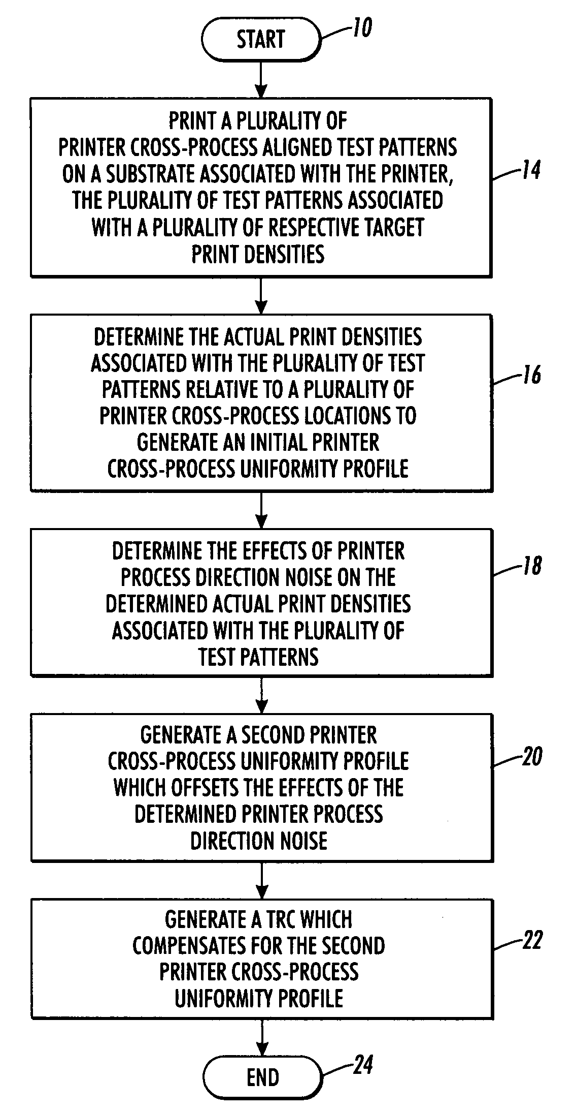
[0013]According to one aspect of this disclosure, a method of compensating for printer cross-process nonuniformities is described. The method of compensating comprises (a) printing a plurality of printer cross-process aligned test patterns on a substrate associated with the printer, the plurality of test patterns comprising a plurality of print densities associated with a plurality of respective target print densities, wherein the plurality of test patterns are configured to subsequently quantify printer process direction noise associated with the printer; (b) determining the actual print density associated with the plurality of test patterns relative to a plurality of printer cross-process locations to generate an initial printer cross-process uniformity profile; (c) determining the effects of printer process direction noise on the determined actual print densities associated with the plurality of test patterns; (d) generating a second printer cross-process uniformity profile which offsets the effects of the determined printer process direction noise; and (e) generating a TRC which compensates for the second printer cross-process uniformity profile.
[0014]According to another aspect of this disclosure, a computer program product is described. The computer program product comprises a computer-usable data carrier storing instructions that, when executed by a computer, causes the computer to perform a method of compensating for printer cross-process nonuniformities comprising (a) printing a plurality of printer cross-process aligned test patterns on a substrate associated with the printer, the plurality of test patterns comprising a plurality of print densities associated with a plurality of respective target print densities, wherein the plurality of test patterns are configured to subsequently quantify printer process direction noise associated with the printer; (b) determining the actual print density associated with the plurality of test patterns relative to a plurality of printer cross-process locations to generate an initial printer cross-process uniformity profile; (c) determining the effects of printer process direction noise on the determined actual print densities associated with the plurality of test patterns; (d) generating a second printer cross-process uniformity profile which offsets the effects of the determined printer process direction noise; and (e) generating a second TRC which compensates for the second printer cross-process uniformity profile.

Problems solved by technology

Typical defects might arise from a non-uniform LED imager, contamination of the high voltage elements in a charger, scratches in the photoreceptor surface, etc.
Often though, such precision manufacturing will prove to be cost prohibitive.
These errors are called process direction noise.
This noise will lead to an imperfect measurement of the engine response curve (ERC), thus an error in the printer model and an imperfect compensation.
In addition, the toner area coverage sensors are typically designed to measure a fixed position and do not have the capability to move in the cross process direction.
This large beam does not provide the resolution for the toner area coverage sensor to be useful as a sensor for the narrow streaks that may occur for poorly performing subsystems.

Method used


Image

  • Measurement of engine response curve in the presence of process direction noise
  • Measurement of engine response curve in the presence of process direction noise
  • Measurement of engine response curve in the presence of process direction noise

Examples


Embodiment Construction

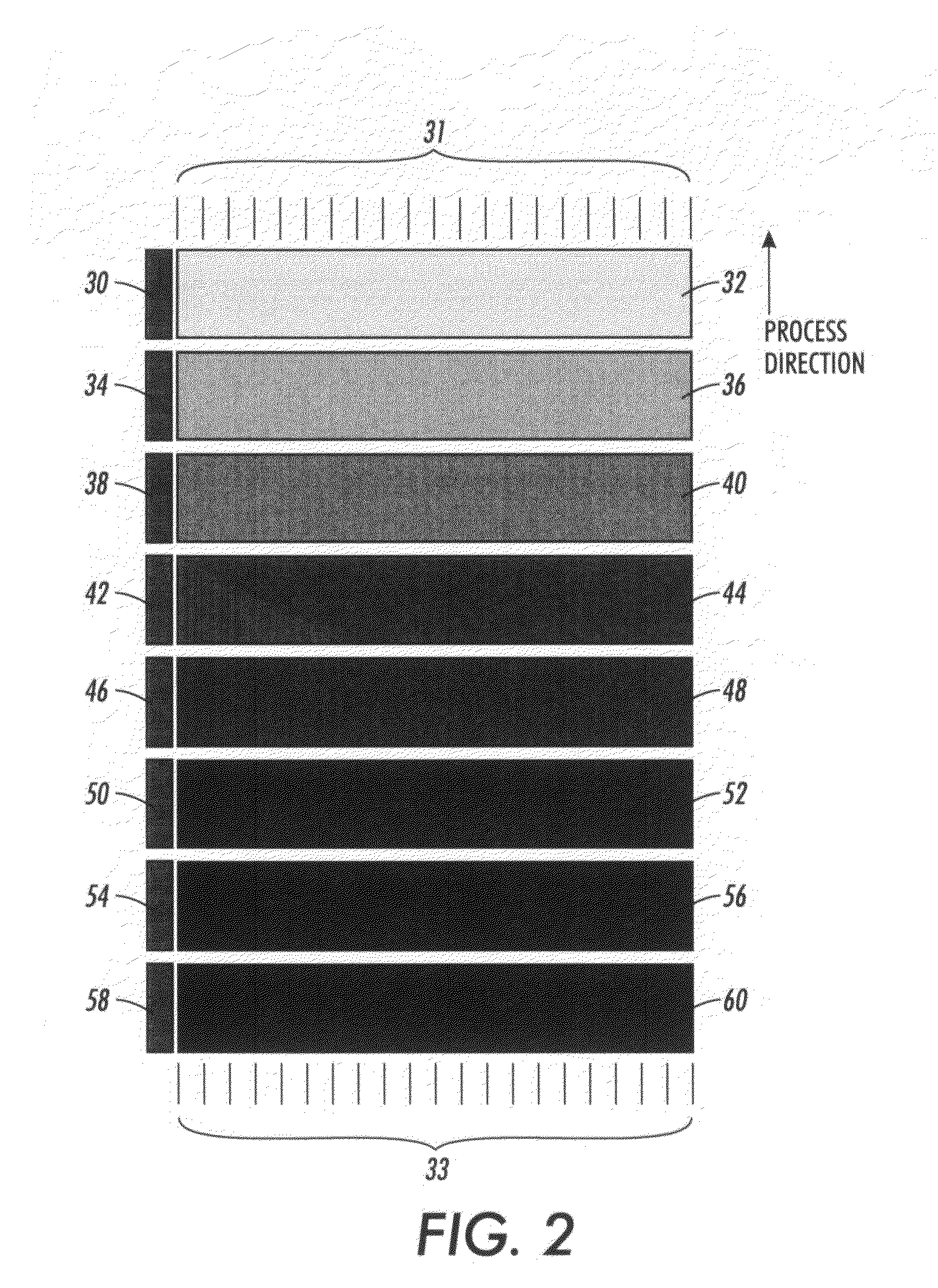
[0023]Disclosed are a variety of techniques to eliminate the variations described in the background section of this disclosure. The common theme of the techniques is that reference patches are applied in various ways to quantify the process direction noise. To summarize, according to one disclosed technique, a calibration gray patch is printed adjacent to every strip. In the presence of process direction noise, the process direction noise is quantified by the response of the calibration patch. The calibration patch response is used to adjust the average gray level of the strip which is being used to monitor the uniformity. According to another disclosed technique, the same gray level strip is printed at different areas along the belt. The difference between the mean of each strip and the global mean over all strips is used to adjust the response of all other patches in its vicinity. In still another disclosed technique, a strip, not just of one gray level but of multiple gray levels...


PUM


Abstract

Disclosed is a method and system for compensating for printer cross-process nonuniformity. The method and system provide a means to offset a cross-process uniformity profile associated with an image output device, such as a printer, where process direction noise is measured and the cross-process uniformity profile is adjusted accordingly to provide a better representation of the image output device cross-process uniformity profile.

Description

BACKGROUND[0001]Defects in the subsystems of a xerographic, electrophotographic or similar image forming system, such as a laser printer, digital copier or the like, may give rise to visible streaks in a printed image. Streaks are primarily one-dimensional defects in an image that run parallel to the process direction. Typical defects might arise from a non-uniform LED imager, contamination of the high voltage elements in a charger, scratches in the photoreceptor surface, etc. In a uniform patch of gray, streaks and bands may appear as a variation in the gray level. In general, “gray” refers to the intensity value of any single color separation layer, whether the toner is black, cyan, magenta, yellow or some other color.[0002]One method of reducing such streaks is to design and manufacture the critical parameters of the marking engine subsystems to tight specifications. Often though, such precision manufacturing will prove to be cost prohibitive.[0003]One technique to eliminate thes...

Claims


Application Information

Patent Timeline
Patent Type & Authority Applications(United States)
IPC IPC(8): G03G15/00
CPCG03G2215/00067G03G15/5062
Inventor MIZES, HOWARDFILLION, CLAUDE S.
Owner XEROX CORP
Learn More