Method of Introduction of Filling Materials in Liquid Form Into Porous Bodies

Active Publication Date: 2009-04-09
AUDI AG
View PDF2 Cites 2 Cited by
  • Summary
  • Abstract
  • Description
  • Claims
  • Application Information

AI Technical Summary

Benefits of technology

[0012]Especially good results are obtained when the filling materials in liquid form are introduced at more than one site within the porous body, the introduction sites preferably being arranged symmetrically. The introduction sites are preferabl

Problems solved by technology

The problem which is common to all these methods is that the silicon melt is always supplied from the surface of the body to be infiltrated.
These gradients lead to inhomogenei

Method used


Image

  • Method of Introduction of Filling Materials in Liquid Form Into Porous Bodies
  • Method of Introduction of Filling Materials in Liquid Form Into Porous Bodies
  • Method of Introduction of Filling Materials in Liquid Form Into Porous Bodies

Examples


Example

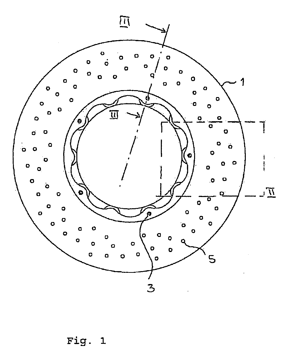
[0021]FIG. 1 shows a top view of a ring disk 1 from the side of the ring disk 1 provided with blind holes 3, in this embodiment five blind holes being located near the inner periphery of the ring disk 1 and each offset by 72°. Perforation drilled holes 5 are distributed over the surface of the ring disk.

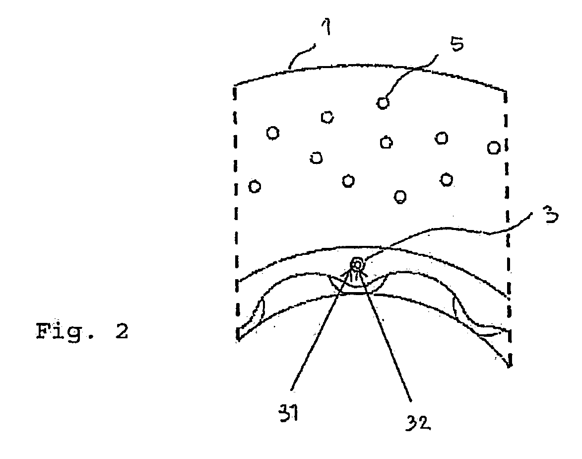
[0022]FIG. 2 shows a cutaway view of this top view, a blind hole being shown enlarged. Both the drilled hole 31 with the larger diameter and also the drilled hole 32 with the smaller diameter can be recognized from overhead. The perforation drilled holes through the ring disk are designated as 5.

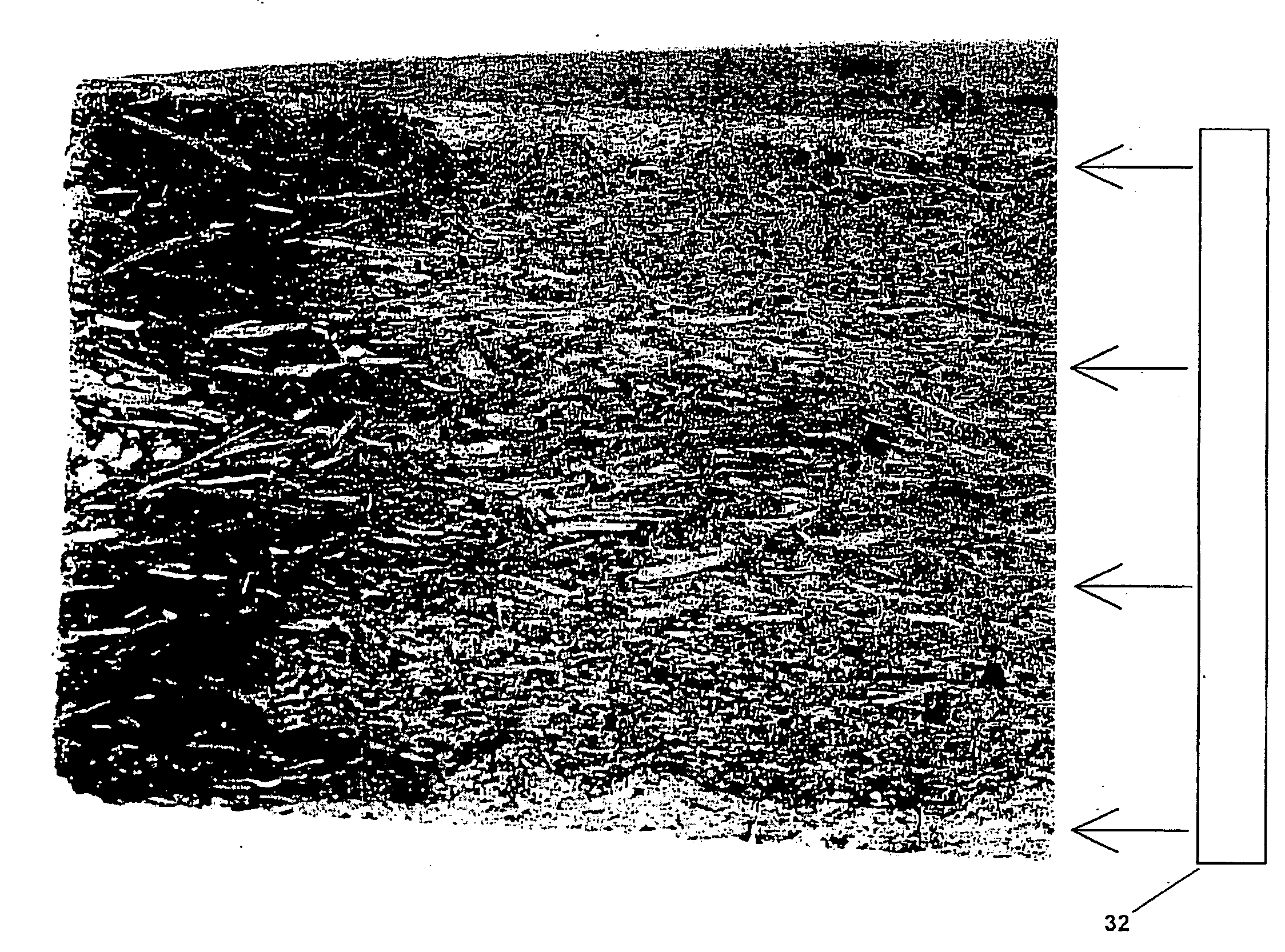
[0023]FIG. 3 shows a section through a ring disk 1 along the plane which is spanned by the axis of rotation of the ring disk 1 and the segment III-III. In the right part of the figure there is a blind hole 3 into which the wick 4 is inserted. As a result of the orientation of the pores, which in the case of wicks of carbonized wood are preferably aligned in the longitudinal axis of the wicks ...


PUM

PropertyMeasurementUnit
Temperatureaaaaaaaaaa
Fractionaaaaaaaaaa

Abstract

Method for introduction of filling materials into porous bodies in which the filling materials in liquid form are brought into contact with the porous bodies and are distributed from at least one site within the porous body in this porous body.

Description

CROSS-REFERENCE TO RELATED APPLICATIONS[0001]This application claims priority from German Patent Application No. 10 2007 044 122.5 filed on Sep. 15, 2007, the entire disclosures of which are hereby incorporated by reference.[0002]This invention relates to a method for introduction of filling materials in liquid form into porous bodies. In particular, it relates to a method in which the liquid filling materials after introduction into the porous body react with at least one of its components, with the formation of at least one chemical compound.BACKGROUND OF THE INVENTION[0003]Often in the production of ceramic materials first a porous body is produced by a thermal process step, such as, for example, sintering or pyrolysis, and is then compacted. This compaction can take place by pressing, that is, without adding another substance, or by one or more infiltration or impregnation steps, while the infiltration agent can remain unchanged and at least partially fills only the (open or acc...

Claims


Application Information

Patent Timeline
IPC IPC(8): B32B3/26B05D7/22
CPCC04B35/573Y10T428/30F16D69/02C04B35/806Y10T428/249953Y10T428/249994C04B35/80
Inventor DROZNY, ADAMJOOS, JURGENSTUHLER, GREGOR
Owner AUDI AG
Why Eureka
Try Eureka