High gripping and non-slip belts for pneumatic lumbar traction device

a lumbar traction and high grip technology, applied in the field of pneumatic lumbar traction devices, can solve the problems of reducing the effectiveness of lumbar traction, and achieve the effect of reducing the effect of lumbar traction

Inactive Publication Date: 2009-04-09
GLACIER CROSS
View PDF21 Cites 6 Cited by
  • Summary
  • Abstract
  • Description
  • Claims
  • Application Information

AI Technical Summary

Benefits of technology

[0008]According to the present invention there is provided a pneumatic lumbar traction device of the type disclosed in the Chitwood U.S. Pat. No. 6,045,525 which has an upper smooth surface on which a user will lie, the improvement residing in a chest belt having a pair of straps and clips or buckles for fixing the belt around the chest of a body. The outer surface of the chest belt has hook or loop material for fixing the chest belt to two elongate spaced apart strips of loop or hook material fixed on and to the upper smooth surface of the device. The chest belt has opposite end portions with two first straps fixed on each end portion with a male clip or female clip slidable on the strap and received around a bar in a transverse slot in the clip and an opposed second short strap or tab on the opposite end portion with a female or male clip at an outer end thereof and the first strap can be pulled around the bar in the transverse slot in the first named clip, after the opposed clips are fixed together, thereby to tighten the chest belt around a users chest. The improvement also resides in a pelvic traction belt that is adapted to be received

Problems solved by technology

While this worked well, there was still slippage of the belts or straps on the torso of the body which reduced the effectiveness of the stretching of the lumbar area.
For years, the simplicity of hook and loop fasten

Method used


Image

  • High gripping and non-slip belts for pneumatic lumbar traction device
  • High gripping and non-slip belts for pneumatic lumbar traction device
  • High gripping and non-slip belts for pneumatic lumbar traction device

Examples


Embodiment Construction

)

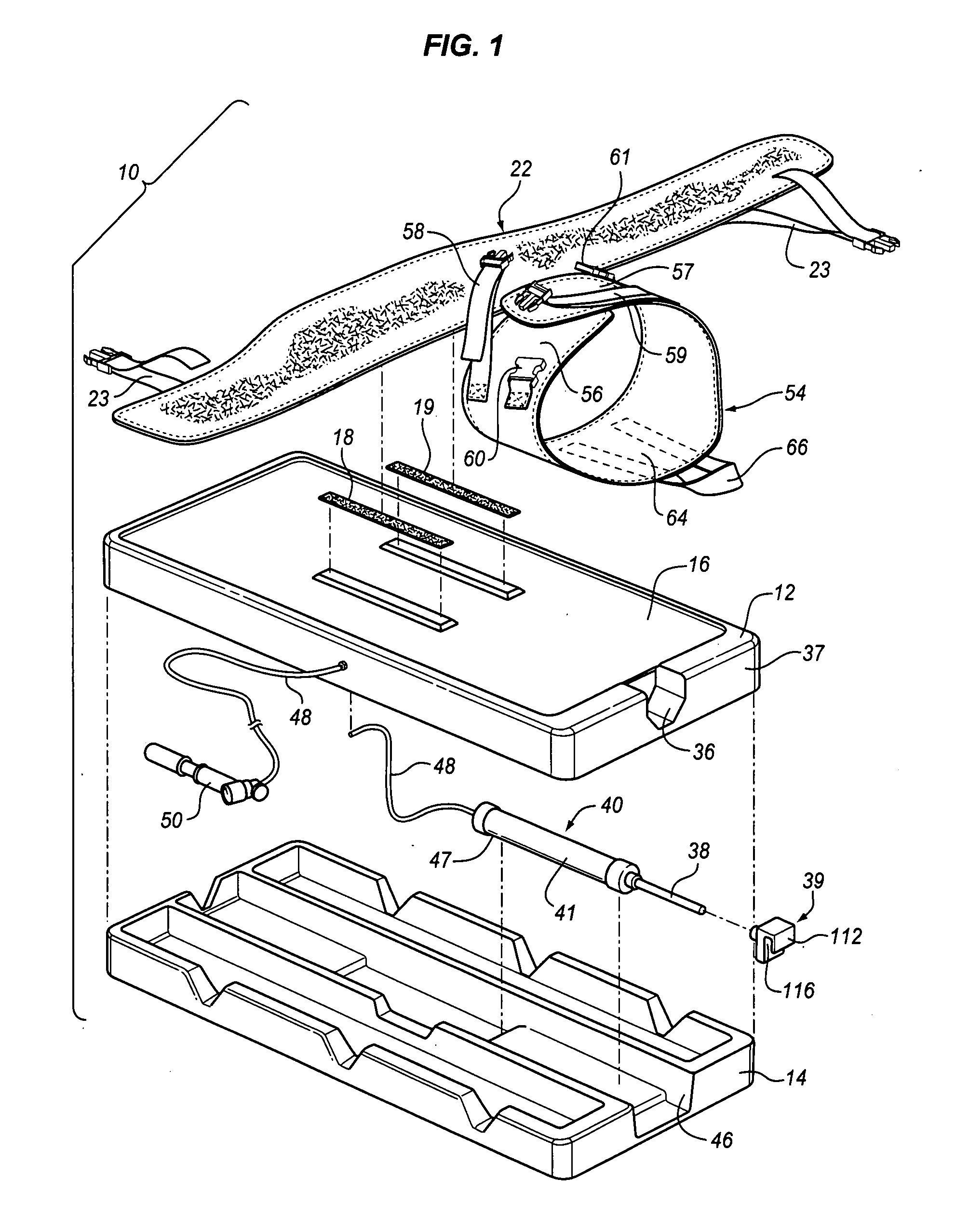
[0017]Referring now to the drawings in greater detail, there is illustrated in FIG. 1 a pneumatic lumbar traction device 10 constructed according to the teachings of the present invention. The device 10 includes an upper, hollow shell part 12 and a lower board, plate or framework part 14.

[0018]The upper, hollow shell part 12 is generally rectangular and constructed and arranged to fit over the lower plate part 14 and has an upper surface 16 which can be a slippery surface, such as by being coated with a lubricous material, i.e., with Teflon®.

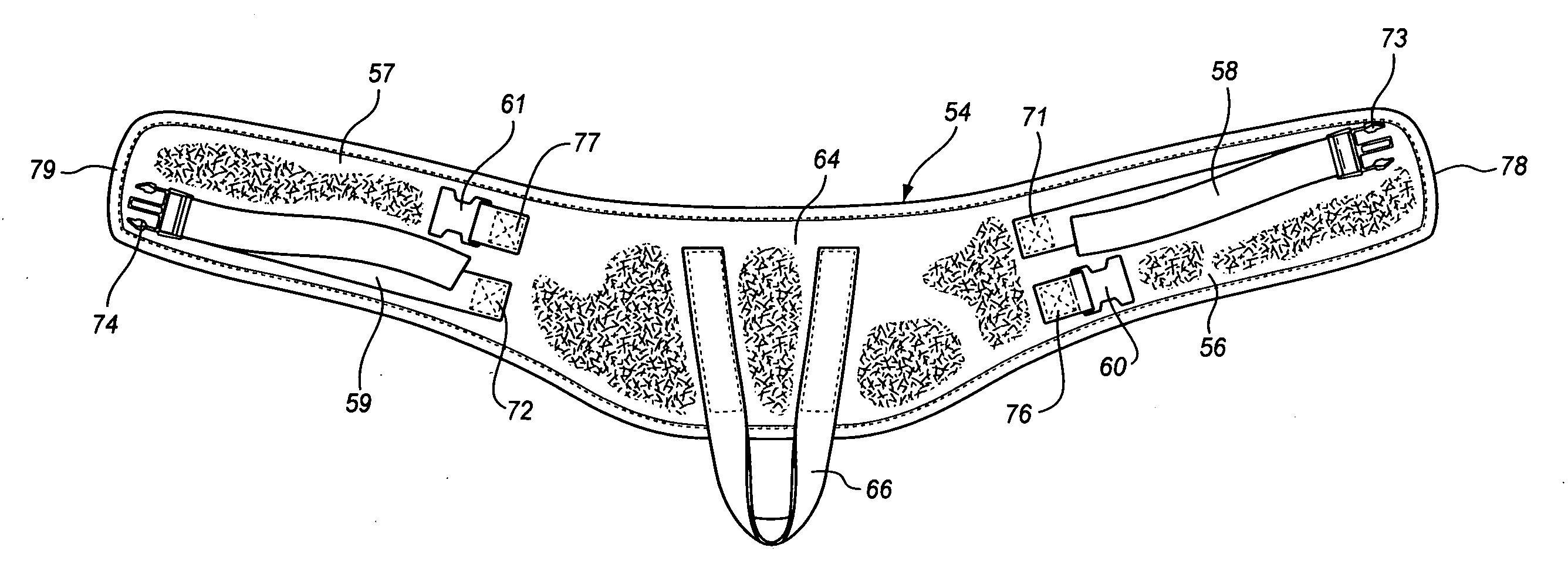
[0019]It is important to note that on the upper surface 16 there are provided two elongate patches 18 and 19 of hook material sold under the trademark Velcro®. The patches 18 and 19 are adapted to engage with loop fabric material 20 on the outside of a chest belt 22 for holding the chest belt 22 to the upper surface 16 of the upper, hollow shell part 12.

[0020]As will be described in detail hereinafter in connection with the description of FIGS....


PUM


Abstract

The pneumatic lumbar traction device comprises two separable parts, namely an upper hollow part and a lower frame, the frame having a pneumatically operated piston and cylinder mechanism fixed in and located centrally therein with a piston rod extending outwardly to engage a bar positioned to engage and move a loop fixed to a pelvic traction belt outwardly of a foot end of the device; the upper hollow part having an upper surface on which a user will lie during use; a generally elongate chest belt having opposite end portions with a strap fixed on each end portion with a first clip on said strap and a mating second clip fixed on the opposite end portion, each strap, after said mating clips are fixed together, being capable of being pulled through said first clip to tighten it on the first clip against said fixed mating second clip thereby to tighten the chest belt around a users chest; two, spaced apart, elongate strips of hook or loop material fixed to a central area of the upper surface for engaging with an outer surface of the chest belt for fixing the chest belt to the upper surface; a pelvic traction belt adapted to be received around the pelvic area of a user and having the loop fixed thereto and extending outwardly transversely of the pelvic traction belt toward the foot end of the device and the pelvic traction belt having opposite end portions with a strap fixed on each end portion with a strap fixed on each end portion with a first clip on said strap and a mating second clip fixed on the opposite end portion, each strap, after said mating clips are fixed together, being capable of being pulled through said first clip to tighten it on the first clip against said fixed mating second clip thereby to tighten the pelvic traction belt around a users pelvic area.

Description

BACKGROUND OF THE INVENTION[0001]1. Field of the Invention[0002]The present invention relates to a pneumatic lumbar traction device which can be placed on the floor or any other horizontal surface, such as a table, and the user thereof can strap himself or herself to an upper surface of the device and then, by pumping a hand pump, can cause a lower pelvic traction belt strapped around the pelvic area of a body to be pulled outwardly from a foot end of the device with a chest belt fixed on the chest of the body holding the user to the upper surface of the device. More specifically, the present invention relates to improved pelvic and chest belts which improve fixing of the belts on the body to minimize slippage of the belts on the body and improve traction on the body with lubricious material on the outer surface of the pelvic traction belt to enhance sliding of the pelvic traction belt on the upper surface of the device.[0003]2. Description of the Prior Art[0004]Heretofore various t...

Claims


Application Information

Patent Timeline
IPC IPC(8): A61F5/00
CPCA61F5/04A61F5/028
Inventor CHITWOOD, NATHANNICKELL, SUSAN
Owner GLACIER CROSS
Why Eureka
Try Eureka