Speed control system for vehicles

a technology of speed control and vehicle, which is applied in the direction of braking system, using reradiation, instruments, etc., can solve the problems of variable deceleration output, driver may not be able to feel the comfort of acceleration, and the feeling of deceleration at this time is not always comfortable for the driver

Active Publication Date: 2009-04-09
DENSO CORP
View PDF19 Cites 88 Cited by
  • Summary
  • Abstract
  • Description
  • Claims
  • Application Information

AI Technical Summary

Benefits of technology

[0017]It is therefore an object of the invention is to provide a speed control system for

Problems solved by technology

The feeling of deceleration at this time is not always comfortable for the driver.
Therefore, the driver may not be able to feel the comfortableness of acceleration depending on the driving scene.
As a result, the deceleration output is varied and discomfort is brought to the driver at the time of deceleration.
Ho

Method used


Image

  • Speed control system for vehicles
  • Speed control system for vehicles
  • Speed control system for vehicles

Examples


first embodiment

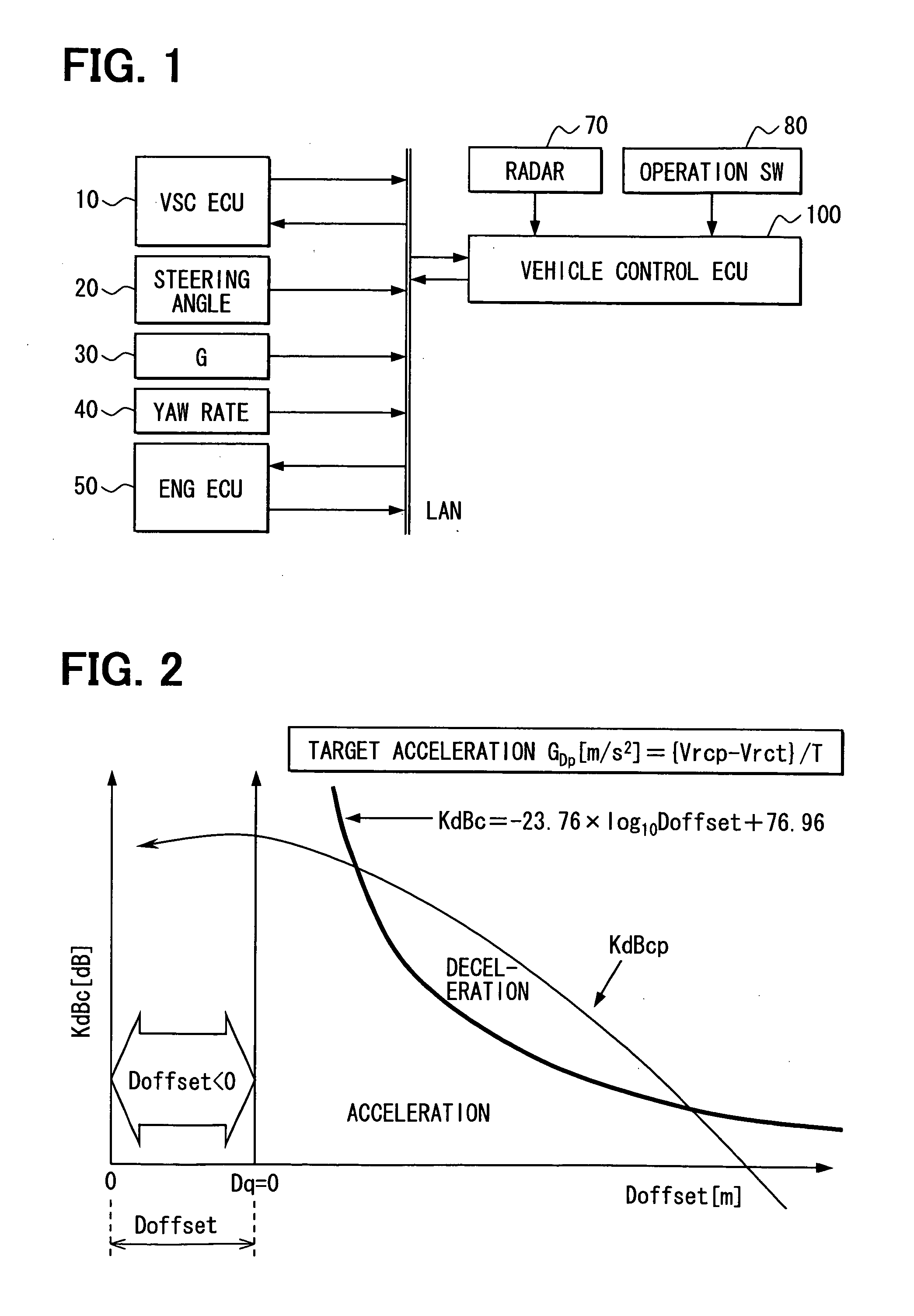
[0063]Referring to FIG. 1, a speed control system for vehicles is applied to a drive assistance system as an example. The drive assistance system is mounted on a subject vehicle (not shown) and constructed of a vehicle stability control (VSC) electronic control unit (ECU) 10, a steering angle sensor 20, a G sensor 30, a yaw rate sensor 40, engine (ENG) ECU 50, a radar 70, an operation switch group (SW) 80, and a vehicle control ECU 100.

[0064]The VSC ECU 10 controls a brake actuator (not shown) that applies braking force to the subject vehicle and has a vehicle stability control function for suppressing skidding of the subject vehicle. The VSC ECU 10 receives information on a target deceleration through an in-vehicle LAN and controls the brake actuator so that this target deceleration is produced in the subject vehicle. The VSC ECU 10 transmits information on the speed (subject vehicle speed) Vs0 and braking pressure of the subject vehicle to the in-vehicle LAN.

[0065]The steering ang...

second embodiment

[0080]In the second embodiment as well, a drive assistance system may be configured in the same way as the first embodiment.

[0081]However, the formula for computation of corrected target relative speed, expressed by Expression 11, is stored in a storage device, such as the ROM, internal to the vehicle control ECU 100 or a storage device provided separately from the vehicle control ECU 100:

Vrtafter=Vr0-Vr0-VroffsetVr0×{Vr0+2.5×D3×10(-1.303D0×D+0.1×KdB0-6.697)}(Expression11)

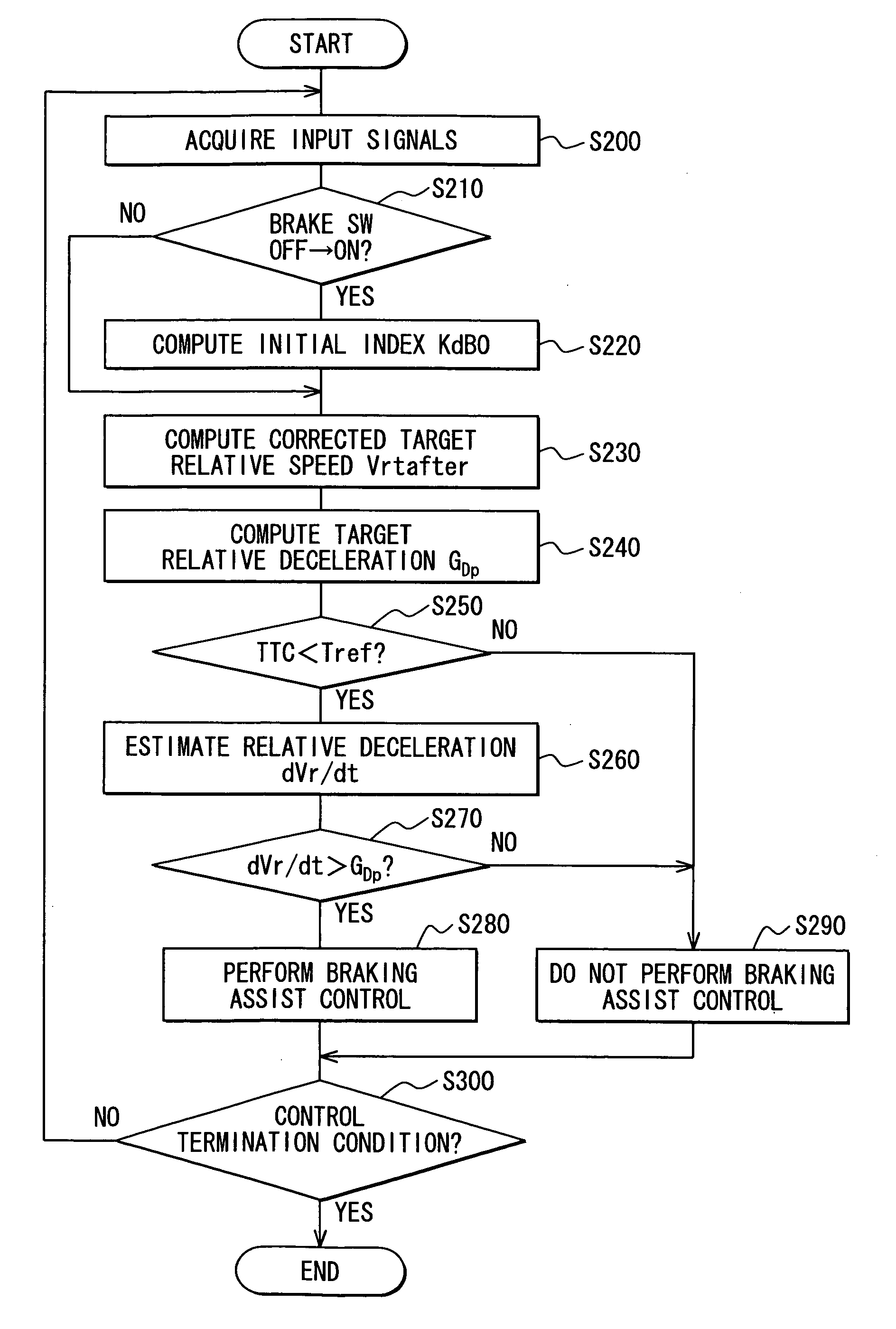
[0082]When a deceleration control start condition is met, the vehicle control ECU 100 carries out deceleration control using Expression 11 above.

[0083]Expression 11 is obtained by taking the following measure. With respect to the formula for computation of target relative speed expressed by Expression 6, the target relative speed at distance D=0 is offset to the positive side by the offset relative speed Vroffset. From D=D0 to 0, the formula for computation is varied at a relative speed obtained by multiplying the ...

modification to second embodiment

[0093]The formula for computation of corrected target relative speed (Expression 11) used in the second embodiment is an expression obtained by multiplying the target relative speed Vrt that can be computed by Expression 6 by the ratio “a”. Instead, Expression 16, obtained by adding the following term to the target relative speed Vrt that can be computed by Expression 6, may be used in place of Expression 11: a term obtained by multiplying the ratio of the travel distance (D0-D) since the start of control to the distance D0 at the start of control by the offset relative speed Vroffset:

Vrtafter=-2.5×D3×10(-1.303D0×D+0.1×KdB0-6.697)+(VroffsetDo)×(D0-D)(Expression17)

[0094]FIG. 8 illustrates comparison between a curve C3 represented by the formula for computation of corrected target relative speed of Expression 16 and the curve C1 represented by Expression 6 (formula for computation of target relative speed).


PUM


Abstract

In a vehicle speed control system, a preset offset distance is taken as a zero value of an inter-vehicle distance in a brake discriminant. When the current value of a corrected distance condition evaluation index is higher than the brake discriminant, a value on the brake discriminant is set as a target value of the corrected distance condition evaluation index. Deceleration control is started to decelerate the subject vehicle so that the deceleration of the subject vehicle becomes equal to the target deceleration of the subject vehicle computed based on the target relative speed corresponding to the set target value and the actual relative speed.

Description

CROSS REFERENCE TO RELATED APPLICATION[0001]This application is based on and incorporates herein by reference the whole contents of Japanese Patent Applications No. 2007-263683 filed on Oct. 9, 2007, No. 2008-97536 filed on Apr. 3, 2008, and No. 2008-127664 filed on May 14, 2008.FIELD OF THE INVENTION[0002]The present invention relates to a speed control system for vehicles.BACKGROUND OF THE INVENTION[0003]In conventional inter-vehicle distance control systems, the enhancement of response to inter-vehicle distance control between a subject vehicle and a preceding vehicle traveling ahead the subject vehicle and the securement of safety are achieved by taking the following measure.[0004]For example, in the inter-vehicle distance control device described in Patent Document 1 (JP 2567548), when the vehicle speed of the subject vehicle is high and when the inter-vehicle distance is short, the time constant of a filter for relative speed is reduced. When the vehicle speed of the subject v...

Claims


Application Information

Patent Timeline
IPC IPC(8): G06F19/00B60T7/12
CPCB60W10/184B60W30/16B60W2520/105B60W2520/125B60W2520/14B60W2720/106B60W2550/14B60W2550/143B60W2550/306B60W2550/402B60W2550/12B60W2554/4041B60W2552/20B60W2552/00B60W2555/20B60W2556/50B60W2552/30B60W2540/18B60W2552/40
Inventor ISAJI, KAZUYOSHITSURU, NAOHIKO
Owner DENSO CORP
Why Eureka
Try Eureka