Control method for preventing tension measuring roller from slipping relative to continuous rolling strip

A control method and technology for measuring rolls, applied in the field of metal pressure processing, can solve problems such as slippage, and achieve the effect of improving the yield of finished products

Active Publication Date: 2014-08-27
GUANGXI LIUZHOU YINHAI ALUMINUM IND
View PDF8 Cites 22 Cited by
  • Summary
  • Abstract
  • Description
  • Claims
  • Application Information

AI Technical Summary

Problems solved by technology

[0003] The object of the present invention is to provide a control method for preventing the tension measuring roller from slipping relative to the continuous rolling strip. The present invention considers finding the optimal time point for the clutch

Method used


Image

  • Control method for preventing tension measuring roller from slipping relative to continuous rolling strip
  • Control method for preventing tension measuring roller from slipping relative to continuous rolling strip
  • Control method for preventing tension measuring roller from slipping relative to continuous rolling strip

Examples


Embodiment 1

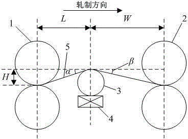
[0078] Set the distance between the center line of the tension measuring roll and the center line of the work roll of the previous frame as 1900mm; the distance between the center line of the tension measuring roll and the center line of the work roll of the next frame is 3600mm; The vertical distance of the line is 200mm; the self-weight of the tension measuring roller is 200kg; the preset tension value between two racks is 12000N; the friction coefficient between the strip and the surface of the tension measuring roller is 0.15. Then the angle between the strip and the horizontal line between the previous frame and the tension measuring roller for:

[0079]

[0080] Then the angle between the strip and the horizontal line between the latter frame and the tension measuring roller for:

[0081]

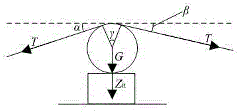
[0082] Wrap angle formed between strip and tension measuring roller for:

[0083]

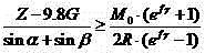
[0084] Under the condition that there is no contact between the strip and the tensi...

Embodiment 2

[0097] Set the distance between the center line of the tension measuring roll and the center line of the work roll of the previous frame as 1900mm; the distance between the center line of the tension measuring roll and the center line of the work roll of the next frame is 3600mm; The vertical distance of the line is 200mm; the self-weight of the tension measuring roller is 200kg; the preset tension value between two racks is 60000N; the friction coefficient between the strip and the surface of the tension measuring roller is 0.11. Then the angle between the strip and the horizontal line between the previous frame and the tension measuring roller for:

[0098]

[0099] Then the angle between the strip and the horizontal line between the latter frame and the tension measuring roller for:

[0100]

[0101] Indicates that the actual tension value at this moment has reached the preset value, namely .

[0102] Wrap angle formed between strip and tension measuring roller...


PUM

PropertyMeasurementUnit
Radiusaaaaaaaaaa

Abstract

The invention discloses a control method for preventing a tension measuring roller from slipping relative to a continuous rolling strip. The method comprises that correlation coefficients are measured in advance; after a rolling mill unit begins to thread the strip, a system determines whether slipping exists between the strip and the tension measuring roller in real time through a critical condition discriminant; when the critical condition discriminant is not met, an electromagnetic clutch keeps a closed state, and the tension measuring roller is transmitted through a motor directly; when the critical condition discriminant is met, the electromagnetic clutch is separated, and the tension measuring roller is transmitted through the strip; when the action tension value reaches or exceeds the preset tension value, the system continues to increase the tension value continuously if determining that slipping still exists, till the system determines slipping is absent to separate the electromagnetic clutch, and the tension measuring roller is transmitted by the strip. By means of the control method, the tension measuring roller can be transformed into an inertia roller at the appropriate time and overcome slip relative to the strip, the lower surface of the strip can be effectively protected, and the tension measuring roller service life can be prolonged.

Description

technical field [0001] The invention relates to the technical field of metal pressure processing, in particular to a control method for preventing slipping of tension measuring rollers between hot continuous rolling mills when they contact strips. Background technique [0002] When the hot continuous rolling mill is rolling the strip, it needs to contact the strip by raising the tension measuring roller between the stands. Its purpose is to measure the tension of the strip after being stretched, and on the other hand, because the height of the tension measuring roller is slightly higher than the rolling elevation line, it can play a certain tension on the strip. The tension measurement roller is driven by a motor, but if the rotation speed of the tension measurement roller driven by the motor does not match the speed of the strip, the tension measurement roller and the lower surface of the strip will slip, which not only damages the quality of the lower surface of the strip,...

Claims


Application Information

Patent Timeline
IPC IPC(8): B21B37/48B21B37/52
Inventor 许磊刘栩蒋婷
Owner GUANGXI LIUZHOU YINHAI ALUMINUM IND
Why Eureka
Try Eureka