
Housings for electronic components

a technology for electronic components and housings, applied in the field of housings for electronic components, can solve the problems of relatively heavy metal housings and high manufacturing costs, and achieve the effects of reducing manufacturing costs, ensuring safety of electrical or electronic components, and reducing manufacturing costs

Active Publication Date: 2009-04-16
HONEYWELL INT INC
View PDF14 Cites 48 Cited by
  • Summary
  • Abstract
  • Description
  • Claims
  • Application Information

AI Technical Summary

Benefits of technology

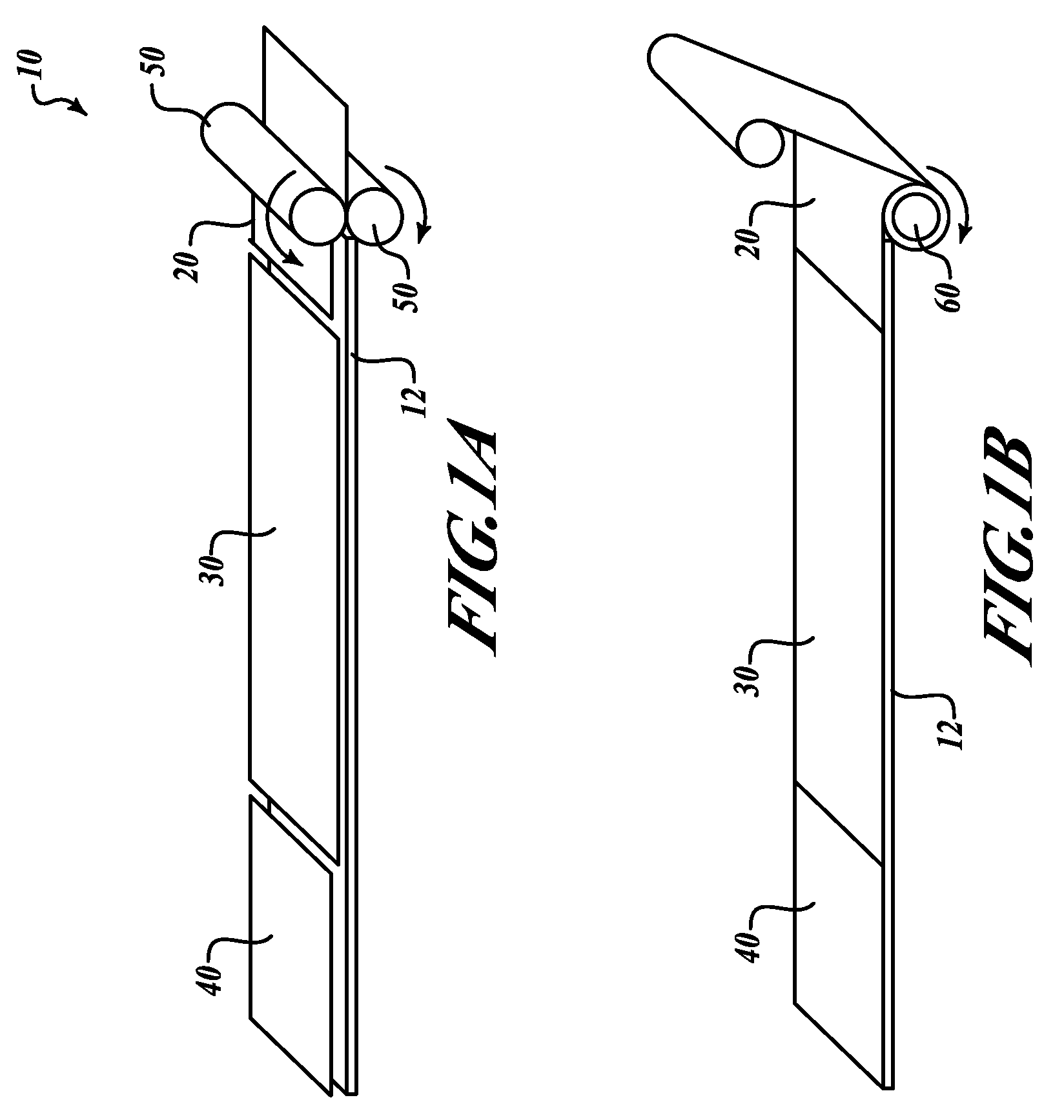
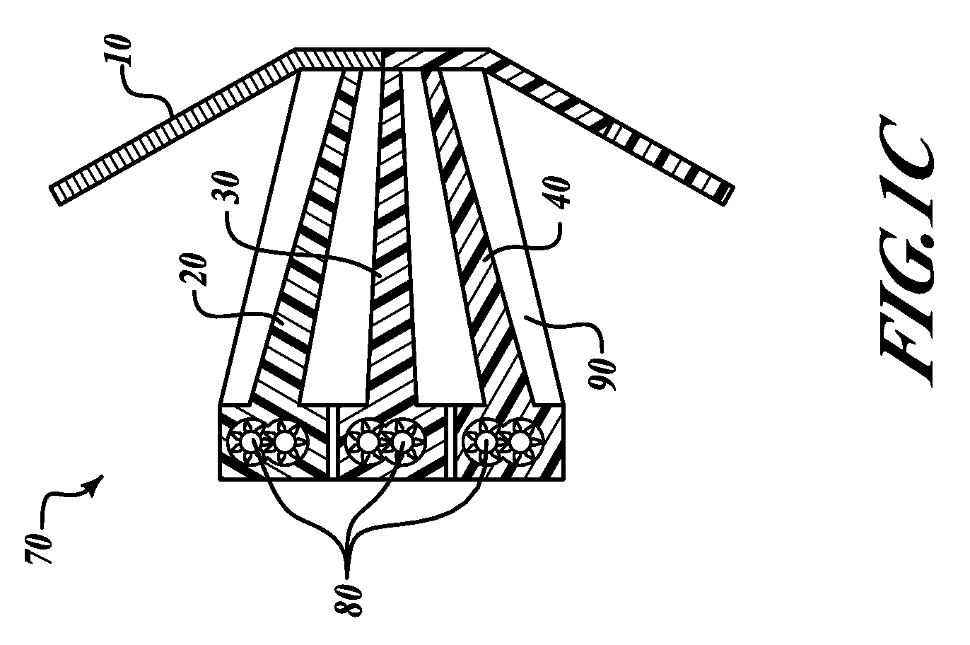
[0009]As will be readily appreciated from the foregoing summary, the invention provides housings for electrical or electronic components that provide shielding from electromagnetic radiation, means for facilitating heat removal, and sufficient mechanical integrity to safely house the electrical or electronic components; these housings are of lighter weight and may be more easily manufactured than previously used housings

Problems solved by technology

However, metal housings have the disadvantage of being relatively heavy and, if machining is involved, relatively expensive to manufacture.

Method used


Image

  • Housings for electronic components
  • Housings for electronic components
  • Housings for electronic components

Examples


example

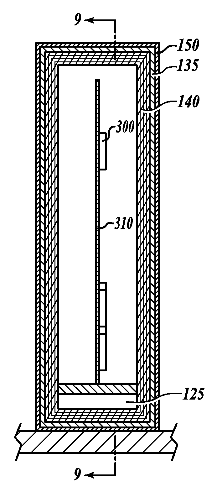
[0039]To illustrate the fabrication process, an approximately quarter-scale electronics chassis was fabricated using available materials. The fabricated chassis corresponds to the design shown in FIG. 7 and is shown in perspective in FIG. 10. The mandrel (not shown) was a 4″×4″×4″ cube made of wood, which was cut into two approximately equal nearly rectangular sections. The cut was made at a slight angle to facilitate sliding removal of the mandrel sections following cure; the two sections were held together by two plates each secured by four screws. An aluminum frame 200 was made from sections of L-channel 0.0625-inch thick and extended along the mandrel by 0.5 inch and had thin (0.25 inch) top and bottom sections 202 which served as the boundary for the wrap layers 150. The dimensions on the face of the frame were selected to just cover the wrap 150 which was approximately 0.15-0.19 in thick. The two sides of the frame extended 0.75 inches and contained openings 210 for the introd...


PUM

PropertyMeasurementUnit
Lengthaaaaaaaaaa
Flow rateaaaaaaaaaa
Widthaaaaaaaaaa

Abstract

Housings for electrical or electronic components made using braid or woven fabric sheets having multiple sections treated with different materials as well as processes and materials for making such housings are disclosed.

Description

BACKGROUND OF THE INVENTION[0001]Housings for electric and electronic components, in addition to having mechanical properties sufficient to support internal components and resist external force, must in some instances also provide shielding from electromagnetic radiation in order to ensure proper functioning of the electronic components. In many cases, it is also necessary for electronic housings to facilitate the removal of heat generated by the electronics. For these reasons, housings are often made of metal to provide the necessary strength, electromagnetic radiation shielding and heat removal capability. However, metal housings have the disadvantage of being relatively heavy and, if machining is involved, relatively expensive to manufacture.[0002]Accordingly, there is a need for light weight housings for electrical or electronic components that provide shielding from electromagnetic radiation, facilitate heat removal, and have sufficient strength to safely house the electrical o...

Claims


Application Information

Patent Timeline
IPC IPC(8): H01L23/06B32B33/00B05D3/02B05D5/00B29C53/56
CPCB29B15/122B29C70/086B29C70/222B29C70/32B29C70/86H05K9/0062B29K2105/0032B29K2105/165B29K2705/00B29K2707/04H05K7/1425B29K2105/0026Y10T442/2631Y10T442/20Y10T442/259
Inventor STEVENSON, JAMES F.VACANTI, DAVID C.LUI, SIU-CHING D.
Owner HONEYWELL INT INC
Learn More