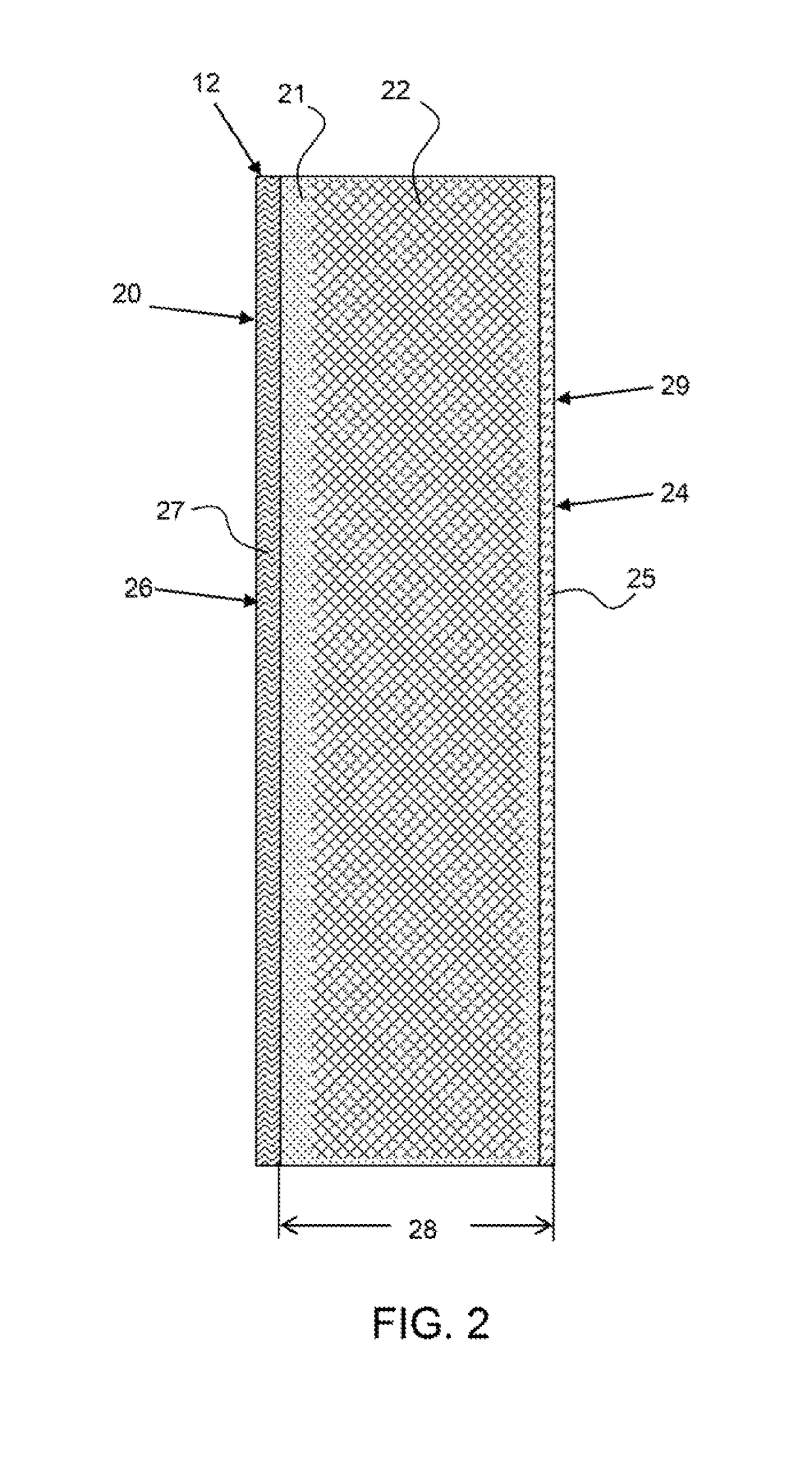
[0011]Any suitable ionomer membrane may be used including, perfluorosulfonic acid ionomer membranes, such as NAFION® available from DuPont Inc., or a supported ionomer membrane, or composite membrane, having a support structure and at least one type of ionomer, such as Gore-Select® membranes available from W.L. Gore and Associates. A support structure may be an expanded polytetrafluoroethylene membrane, ePTFE membrane, that is imbibed with an ionomer. A composite or supported membrane may be much thinner than a cast ionomer membrane, as the support structure restrains the ionomer and provides mechanical support. Composite membranes may be as thin as about 25 μm or less, about 20 μm or less, about 15 μm or less, or any range between and including the thicknesses provided and still have sufficient mechanical integrity. The thinner the membrane, the less resistance to flow through the membrane and therefore higher flow rates of water.
[0013]In one embodiment, the ionomer membrane is an asymmetric membrane having non-uniform properties from one side, the inlet side, to the opposing side, the outlet side. For example, the inlet side may have exposed ionomer that is hydrophilic and the exit side may comprise an exposed hydrophobic material, such as expanded PTFE membrane and / or a fluoropolymer or fluoropolymer coating containing CF3 groups, which are known to reduce surface energy and render surface hydrophobic as well as oleophobic. The hydrophobic nature on the outlet side may prevent or deter water from re-entering the membrane. In another embodiment, an ionomer membrane, may comprise two different ionomer types, a carboxylic acid or sulfonic acid ionomer, for example. One side may comprise a sulfonic acid ionomer and the opposing side may comprise a carboxylic acid ionomer.
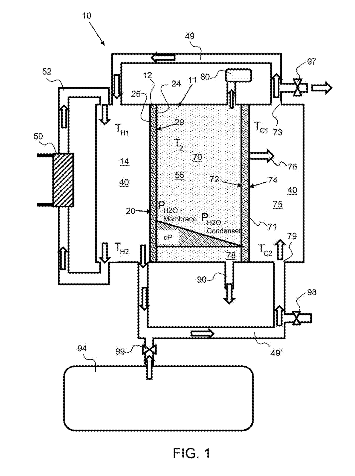
[0016]For a given membrane chemistry, morphology and experimental setup, the water transport through the membrane is a function of the difference in water activity across the membrane. In an exemplary embodiment, the condenser chamber is under vacuum, such as about 0.25 atmospheres or more, about 0.5 atmospheres or more, about 1.0 atmospheres and any range between and including the vacuum pressures provided. The vacuum within the condenser chamber draws the water through the membrane and reduces the activity of water on the condenser side of the membrane. In addition, the water source side, or inlet side, may be heated or be at an elevated temperature with respect to the temperature of the condenser chamber. The water source side may be elevated to a temperature or a temperature differential over the condenser chamber of about 20° C. or more, about 40° C. or more about 50° C. or more, about 40° C. to 80° C. and any temperature range between and including the values provided. A heating loop with a heater in thermal communication with the water in the water source side may be used to heat or maintain a temperature, TH, on the water source side of the water purification system.
[0017]The water source side or a portion thereof, may be a color that increase radiant heat absorption, such as black, to heat water retained therein. In an exemplary embodiment, radiant heat from sunlight is used to provide heat to the water source side or to the heating loop. Likewise, the condenser side may be a color to minimize radiant heat absorption, such as white or a reflective color. The water source side may absorb radiant energy from the sunlight while the condenser side reflect or absorbs far less radiant heat, thereby creating a temperature gradient between the two sides.
[0019]An exemplary water purification system may comprise a latent heat loop that transfer heat from the condenser to the water source side of the ionomer membrane via the source water. A conduit may extend from the water source side of the ionomer membrane to a latent heat chamber inlet and a second conduit may extend from the outlet of the latent heat chamber to the water source side of the ionomer membrane. Source water may circulate through the latent heat loop and conduct the latent heat of vaporization from the latent heat surface of the condenser as it flows over the latent heat surface. The temperature of the source water at the latent heat chamber may be less than the temperature of the source water at the outlet of the latent heat chamber. This use of the latent heat of vaporization increases the efficiency of the system and reduces power requirements.
[0020]In an exemplary embodiment, the water, on the condenser side of the water purification is pumped to the water source side. The water on the condenser side may be heated by the latent heat of vaporization from the water condensing on the condenser surface and this latent heat of vaporization heats the water on the condenser side. By using the condenser exit water as makeup water for the membrane liquid reservoir the heat of vaporization for some / all of the prevaporated water will be returned to the supply side of the membrane. This is mechanically similar to a counter current heat exchanger, however in this case the heat is transferred by pervaporation and condensation. The energy liberated by condensation is returned to the water source side by having the heated cooling water discharge to the membrane water source reservoir or water source side, of the ionomer membrane. In addition, this condensed water flow may be controlled to prevent the membrane liquid reservoir from exceeding salt solubility limits.