Field work vehicle

a field work and vehicle technology, applied in the field of agricultural vehicles, can solve the problems of difficult to do needed work from a large vehicle, and difficult to find workers and pay them enough, etc., to achieve low vehicle profile, low speed, and large ground contact

Inactive Publication Date: 2014-10-21
BULLIS JAMES K
View PDF18 Cites 0 Cited by
  • Summary
  • Abstract
  • Description
  • Claims
  • Application Information

AI Technical Summary

Benefits of technology

[0025]The vehicle is narrow such that it fits in a single row space and enables a worker to sit generally facing forward such that there is access to crops on each side. The seat is capable of being in a very low position whereby the worker can reach to near ground level. The overall vehicle is approximately the same width as the seated worker. Stabilization is provided by a front and a rear wheel set that is configured to give a stable vehicle stance, even though it is exceptionally narrow.
[0026]It was found that a low, thin, and narrow tongue structure suffices as a connection between front and rear wheel structures. The seat provided enables the worker to sit just above the tongue. The main function of the tongue is to lead the rear wheel somewhat like the function of the tongue of a common small trailer towed by an automobile. The tongue structure has a lesser function of carrying loads. Thus, it is possible to achieve adequate mechanical integrity without framing at the side of the vehicle.
[0028]Unlike an unstable situation that would result with pneumatic tires, the present vehicle utilizes hard edges of a large rigid wheel to achieve stability, along with a generally low vehicle profile and a low speed dynamic situation. Center of gravity is controlled such that it is generally lower than the axle of the large wheel.
[0029]This wheel also provides a large footprint ground contact due to both a wide flat lateral surface and extended in line contact, whereby energy efficiency is enhanced.

Problems solved by technology

Some kinds of agricultural work are hard, slow, and uncomfortable.
It is difficult to find workers and pay them enough to get them to do such tasks.
In many situations, the needed work can simply can not be done from a large vehicle because of the need for hand work close to the ground or for workers to be in positions relative to growing crops that would be awkward from large vehicles.
Large vehicles are often not desirable because the crops themselves interfere with access by such vehicles, and unfortunately, this can lead to fanning methods where crop spacing does not make the best possible use of land resources, simply because land must be reserved to allow for the vehicle to pass.
This is adapted to working on low growing crops with over-arching structure that allows passing over crop rows, but all this leads to complicated equipment, when simplicity is needed to allow inexpensive construction.
Some stability would be achieved due to the weight of the low seated worker, when that is the position of the seat, but the conventional tires would not provide the stability of the hard wheel of Ser. No. 13 / 199,968 Bullis 2011.
It appears that stability issues mean that the design of U.S. Pat. No. 2,583,358 is incapable of operating in the very narrow row space that is possible with U.S. Ser. No. 13 / 199,968 Bullis 2011.
A tricycle form of this recumbent bicycle is an obvious variation that can be occasionally seen in use, but this would be still quite useless for the present purpose given that these wheels, though large in diameter, are narrow such that they would sink in soft dirt and cause much resistance to vehicle movement.
Though perhaps this is a useful apparatus, it can not be considered in the category of significant mechanization.
This works fine where there is a pair of widely spaced wheels that achieves stability, but by itself offers little resistance to rolling sidewise.
Because the typical farmer used regular roadways to get tractors from field to field, these lugs caused much disruption of smooth road surfaces.
This vehicle is questionable as to safety given the high seat position, and of course this configuration does not suggest any interest in enabling hand work on low crops.
Though light weight is possible with a box-like general structure, the side panels and upper rails limit access to field crops.
Access to plants at the ground level is troublesome due to both the floor and side structure of this vehicle.

Method used


Image

  • Field work vehicle
  • Field work vehicle
  • Field work vehicle

Examples


Embodiment Construction

[0037]The background art clearly shows limited extension of industrial technology to the agricultural world to provide what could be important changes in agricultural practice. Thus that practice carries on inadequately, seemingly unaware that industrial approaches could minimize the difficulty and discomfort of the work, not to mention what such approaches could do to enhance productivity of both workers and land. Surprisingly, it appears that it is possible to make agriculture significantly more profitable.

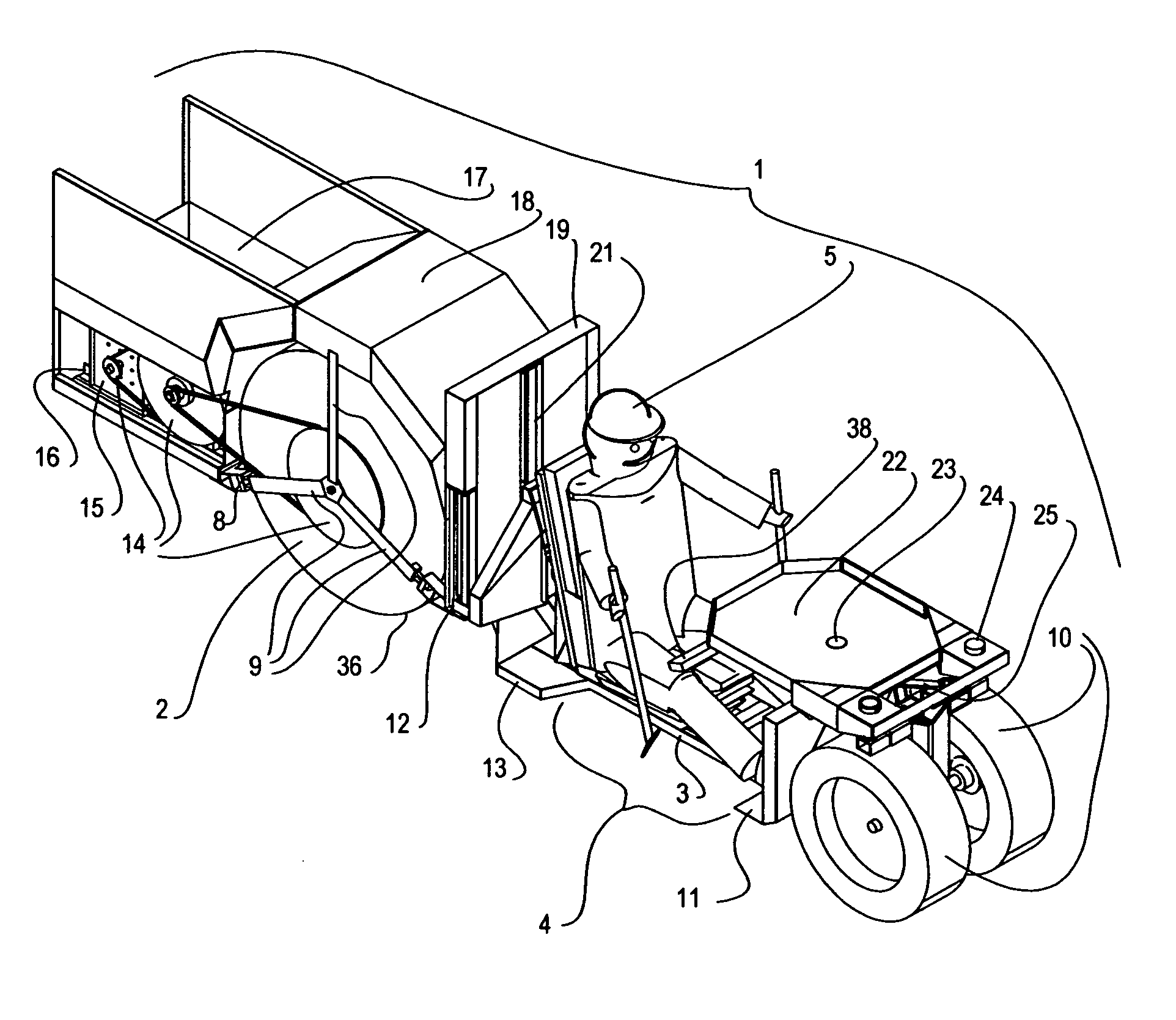
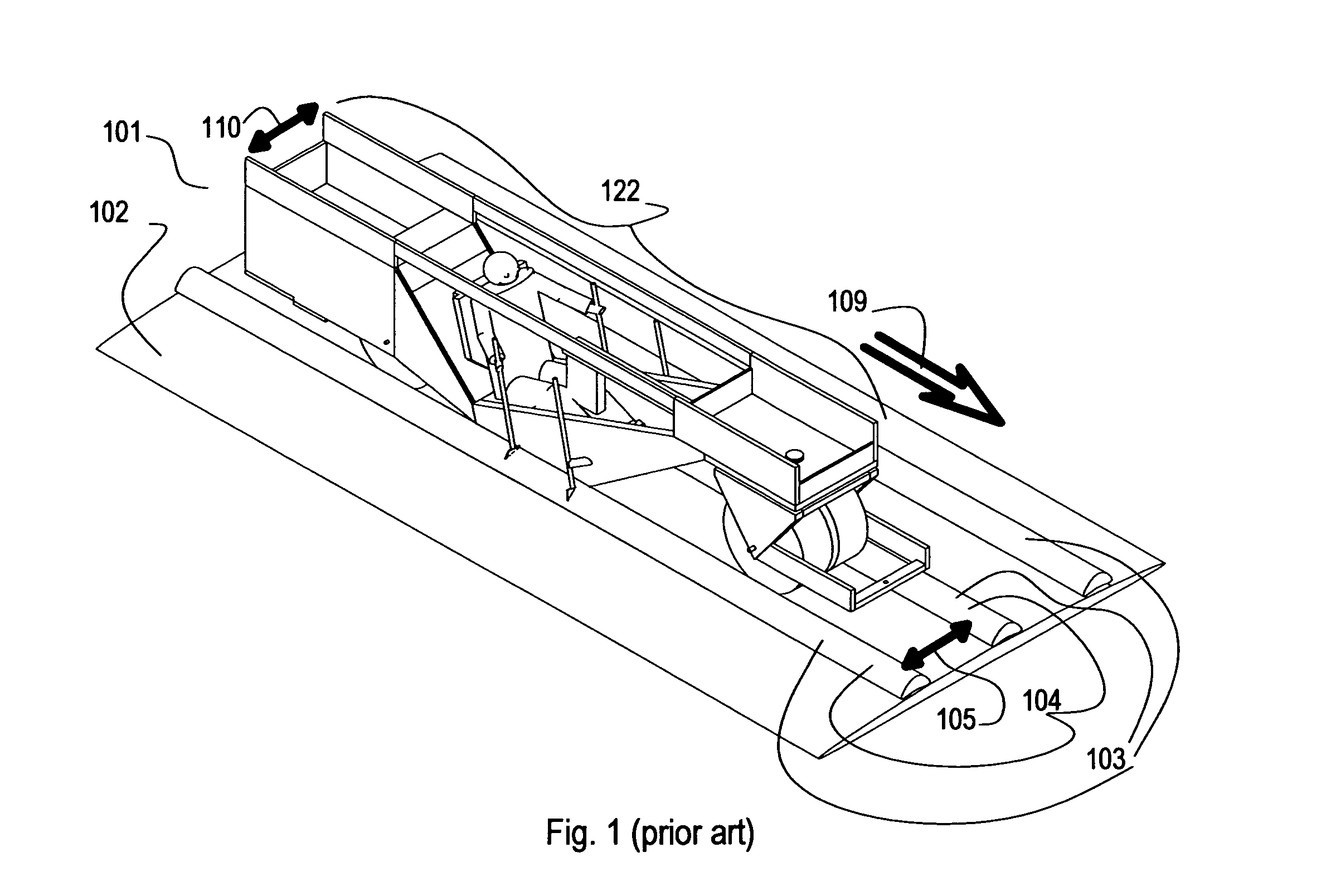
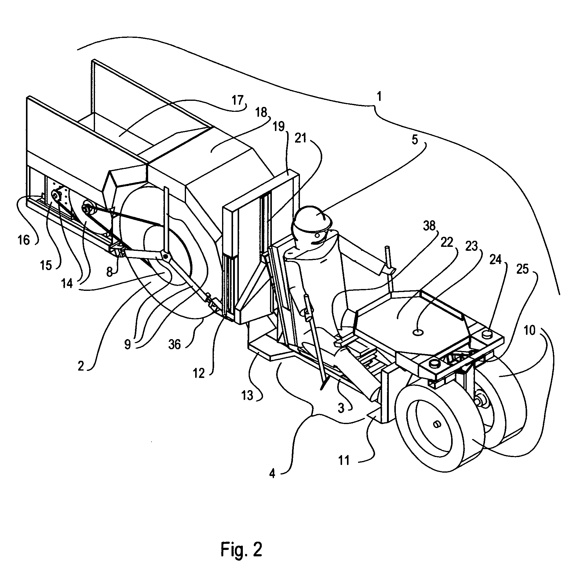
[0038]FIG. 1 (prior art) shows an initial concept vehicle for operating in a single row space and enabling much improved access to crops and much improved working conditions. FIG. 2 illustrates the present invention having similar purposes, but being superior due to more advanced implementation.

[0039]The here invented vehicle 1 utilizes a wide rigid wheel system 2 that provides maximum stability and causes a minimum of energy loss due to earth depression. Front 10 and rear wheel...


PUM


Abstract

Narrow agricultural vehicles have been invented to make farm labor more attractive, to enable enhanced productivity of workers, and to make possible more complete usage of the land.A low seating position is provided for a worker. The width of the vehicle is approximately the same width as the seated worker, enabling vehicle use with narrowly spaced row crops. The wheel set is configured for both maximum stability and efficient operation on soft surfaces, using large drum wheels that maximize the footprint area.The vehicle structure includes a wide frame section and a low and narrow tongue structure that connects between front and rear wheel arrangements. The tongue configuration minimizes interference with work of said worker.

Description

[0001]This patent document contains material that is subject to copyright protection. Facsimile reproduction is allowed of the patent document or the patent disclosure as it appears in the Patent and Trademark Office patent file or records as allowed by US patent law, but otherwise all copyright rights are reserved.BACKGROUND OF THE INVENTION[0002]1. Field of the Invention[0003]This present invention relates to agricultural vehicles.[0004]2. Description of the Prior Art[0005]There is on-going concern for future agricultural productivity, given the expanding world population. This concern is further exacerbated by the practice of using feed grain crops for making motor vehicle fuel. It is paramount that we make the best possible use of agricultural resources. One way to do this is to greatly expand irrigation by distributing water on a continental basis. This enlargement of agricultural operations could lead to a need for far more agricultural workers. Hopefully, we can find a way to...

Claims


Application Information

Patent Timeline
Patent Type & Authority Patents(United States)
IPC IPC(8): B62D55/00
CPCB60N2/38B62D49/00
Inventor BULLIS, JAMES, K.
Owner BULLIS JAMES K
Why Eureka
Try Eureka