Click apparatus

a click apparatus and click technology, applied in the field of click apparatus, can solve the problems of suppressing a clear click feeling and increasing the friction proportionally, and achieve the effect of clear clicking feeling and high click degr

Inactive Publication Date: 2009-04-16
PANASONIC CORP
View PDF6 Cites 9 Cited by
  • Summary
  • Abstract
  • Description
  • Claims
  • Application Information

AI Technical Summary

Benefits of technology

[0019]The present invention solves the conventional disadvantage as described above. The present invention provides a click apparatus that secures a clear click feeling and that provides a high click degree.
[0021]According to this configuration, the pressure by the click springs is applied to the same positions of both of the upper and lower faces of the flange section of the rotation body in a balanced manner. Thus, the rotation body is prevented from being inclined. Thus, friction between the rotation body and the support section member such as the upper case and the lower case can be suppressed, thereby providing a further clearer click feeling and a high click degree.

Problems solved by technology

This has caused a disadvantage that the above friction proportionally-increased due to the increased pressures has suppressed a clear click feeling.

Method used


Image

  • Click apparatus
  • Click apparatus
  • Click apparatus

Examples


embodiments

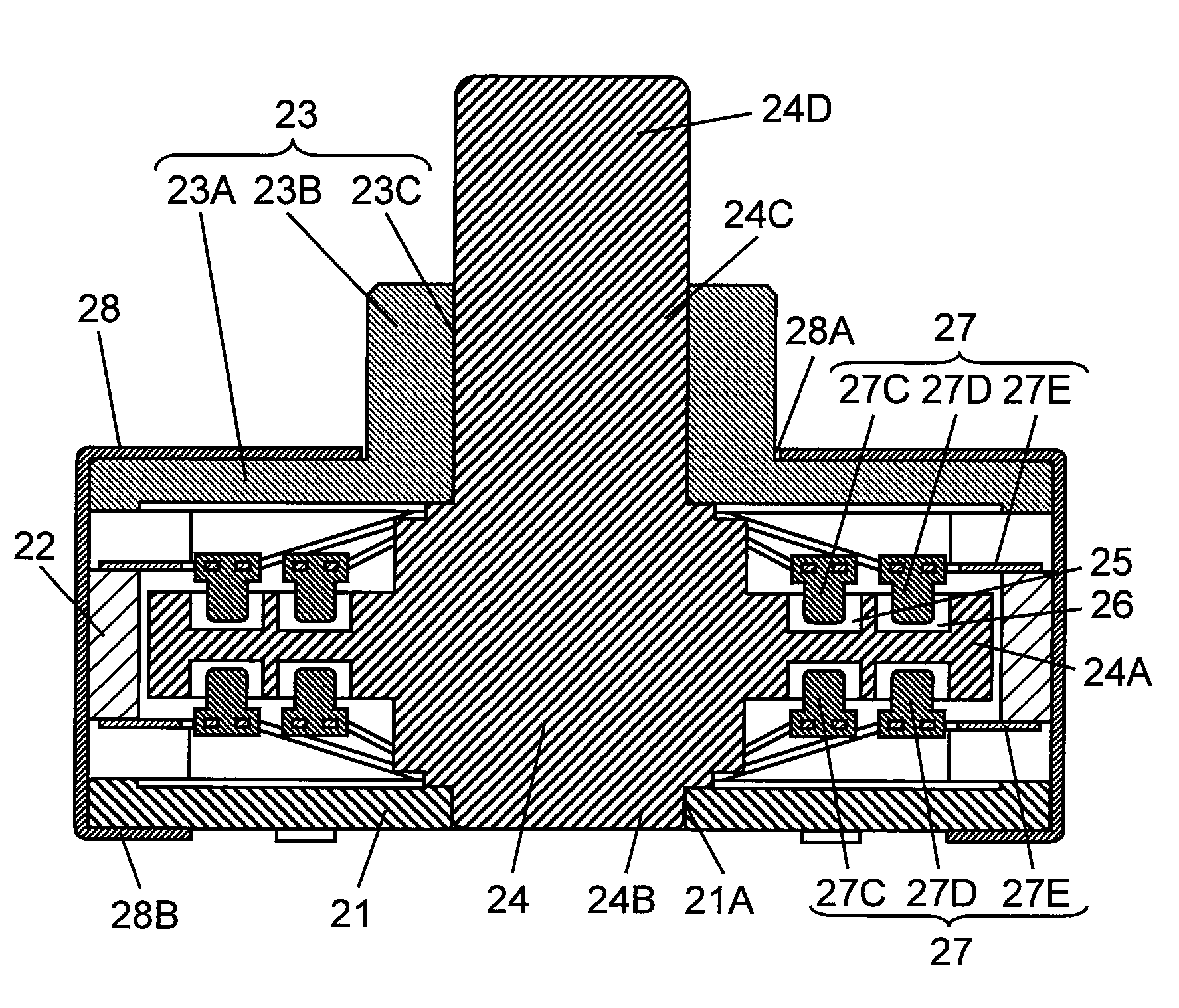
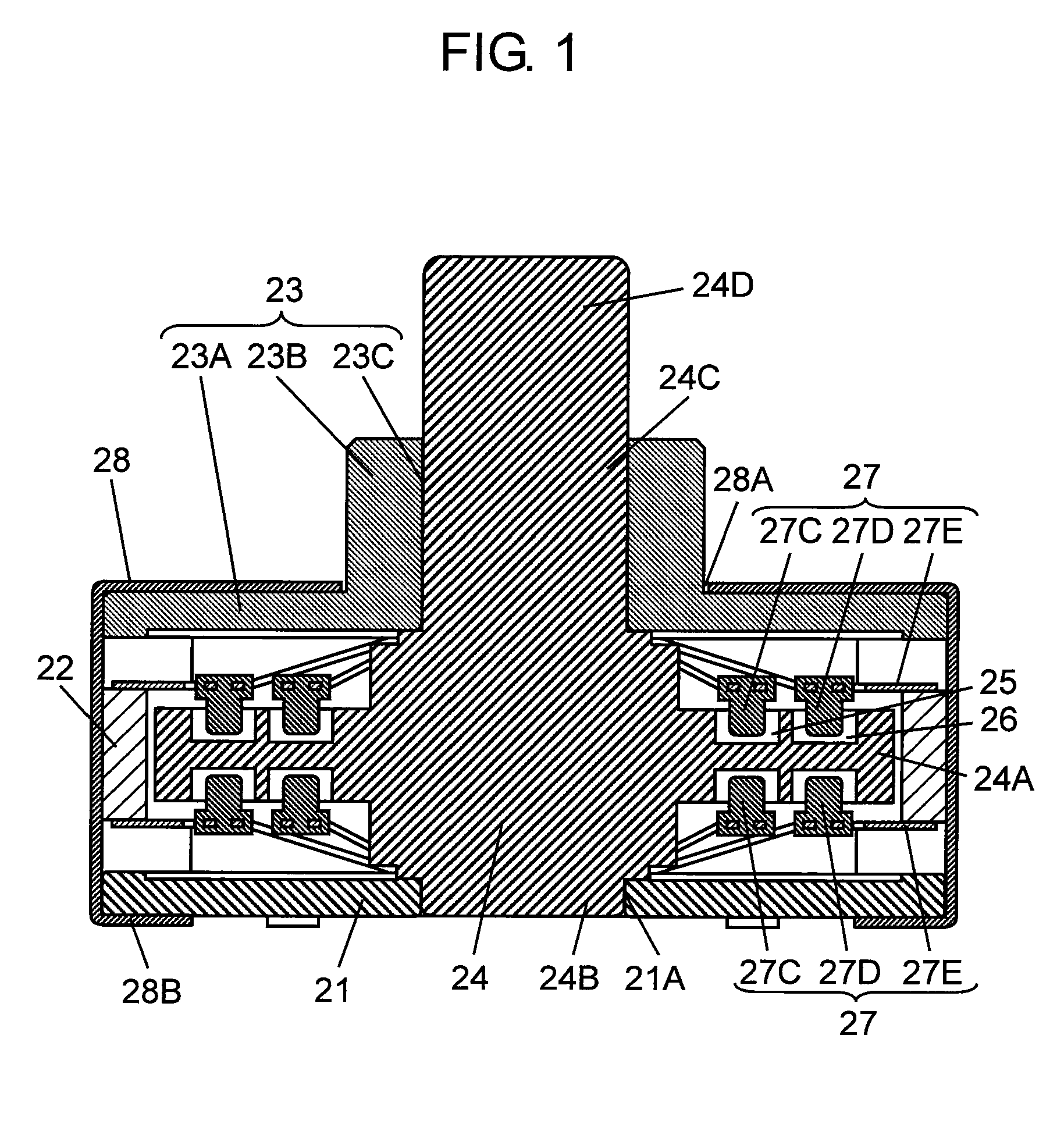
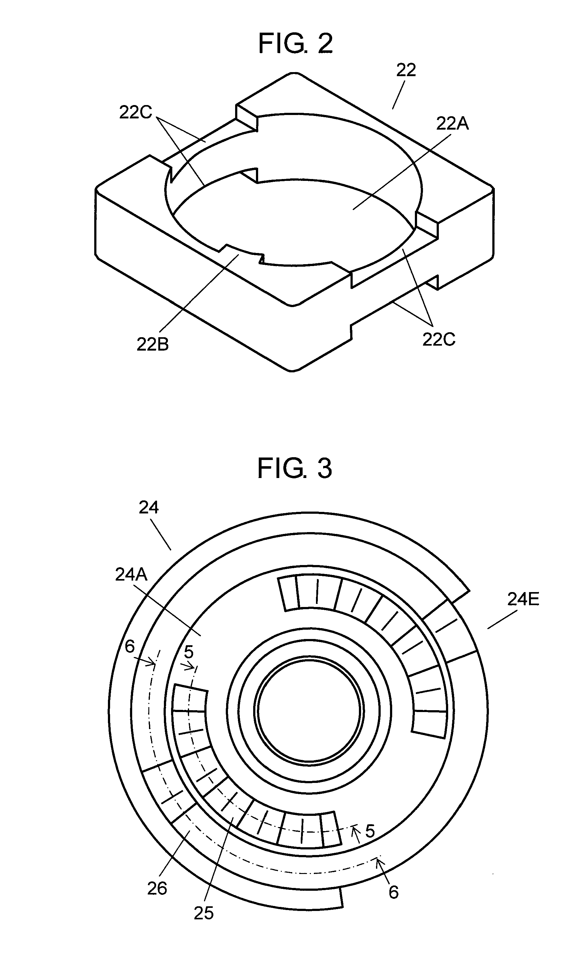
[0050]FIG. 1 is a cross-sectional view illustrating a click apparatus according to one embodiment of the present invention. FIG. 2 illustrates an appearance of an inner case of the click apparatus. FIG. 3 is a plan view illustrating a rotation body of the click apparatus. FIG. 4 is a plan view illustrating a click spring of the click apparatus.

[0051]In FIG. 1, substantially square flat plate-like lower case 21 has circular middle hole 21A at the center thereof. Inner case 22 is formed to have a substantially square frame-like shape, is positioned above lower case 21, and has circular hollow section 22A (see FIG. 2). As shown in FIG. 2, inner case 22 includes lock section 22B that inwardly protrudes to an inner wall forming circular hollow section 22A within a predetermined angle range. At the upper and lower faces of opposed two sides of the frame, dent sections 22C are provided to have a predetermined width and the same depth, respectively.

[0052]In FIG. 1, upper case 23 is position...


PUM


Abstract

At both of the upper and lower faces of flange section (24A) of rotation body (24) rotatably retained between lower case (21) and upper case (23) opposed to each other via inner case (22), inner concavo-convex section (25) and outer concavo-convex section (26) are provided at point-symmetric positions on concentric circles of an inner circumference-side circle and an outer circumference-side circle. Inner elastic contact projection (27C) and outer elastic contact projection (27D) of double ring-like click spring (27) respectively elastically contact inner concavo-convex section (25) and outer concavo-convex section (26) respectively corresponding to both of the upper and lower faces of flange section (24A), thereby providing a clear click feeling and a high click degree.

Description

BACKGROUND OF THE INVENTION[0001]1. Field of the Invention[0002]The present invention relates to a click apparatus that is used for a rotating operation section of an in-vehicle control apparatus such as a car air-conditioner and that generates a click feeling by a rotating operation.[0003]2. Background Art[0004]A rotating operation section of an in-vehicle control apparatus such as a car air-conditioner mainly uses a click-type rotating operation-type electronic component so that operability is obtained and a set position after the operation is prevented from being dislocated. Thus, the click-type rotating operation-type electronic component as described above has been required to have a high click degree in order to prevent the dislocation due to vibration or the like and to prevent a wrong operation.[0005]A conventional click apparatus used for the click-type rotating operation-type electronic component as described above will be described with reference to FIG. 20 and FIG. 21.[0...

Claims


Application Information

Patent Timeline
Patent Type & Authority Applications(United States)
IPC IPC(8): H01H19/00
CPCB60K37/06B60K2350/102H01H19/11G05G5/03G05G5/06G05G1/08B60K2370/126
Inventor MIURA, SEIKISATO, JUNNISHIMOTO, TAKUMI
Owner PANASONIC CORP
Why Eureka
Try Eureka