Transmission Mechanism for Electric Nail Gun

a transmission mechanism and electric nail gun technology, applied in the field of transmission mechanism of electric nail gun, can solve the problems of reducing durability and the lifetime of wires, complex structure of clutch assembly with too many components, etc., and achieve the effect of simplifying the life of wires and clutches

Inactive Publication Date: 2009-04-16
DE POAN PNEUMATIC
View PDF26 Cites 26 Cited by
  • Summary
  • Abstract
  • Description
  • Claims
  • Application Information

AI Technical Summary

Benefits of technology

[0006]What is needed, therefore, is to provide a transmission mechanism for an electric nail gun, which uses a flywheel to rotate a driving wheel so as to drive a rack to further driv...

Problems solved by technology

However, the structure of the clutch assembly is complicated with too many components.
In addition, using a wire to pull the driving s...

Method used


Image

  • Transmission Mechanism for Electric Nail Gun
  • Transmission Mechanism for Electric Nail Gun
  • Transmission Mechanism for Electric Nail Gun

Examples


Embodiment Construction

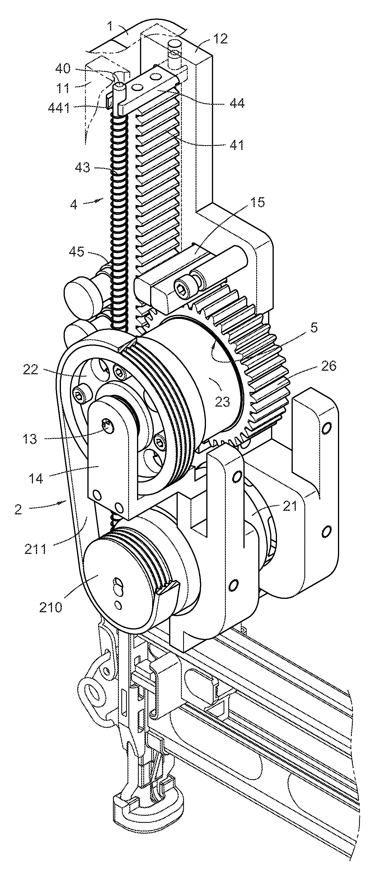
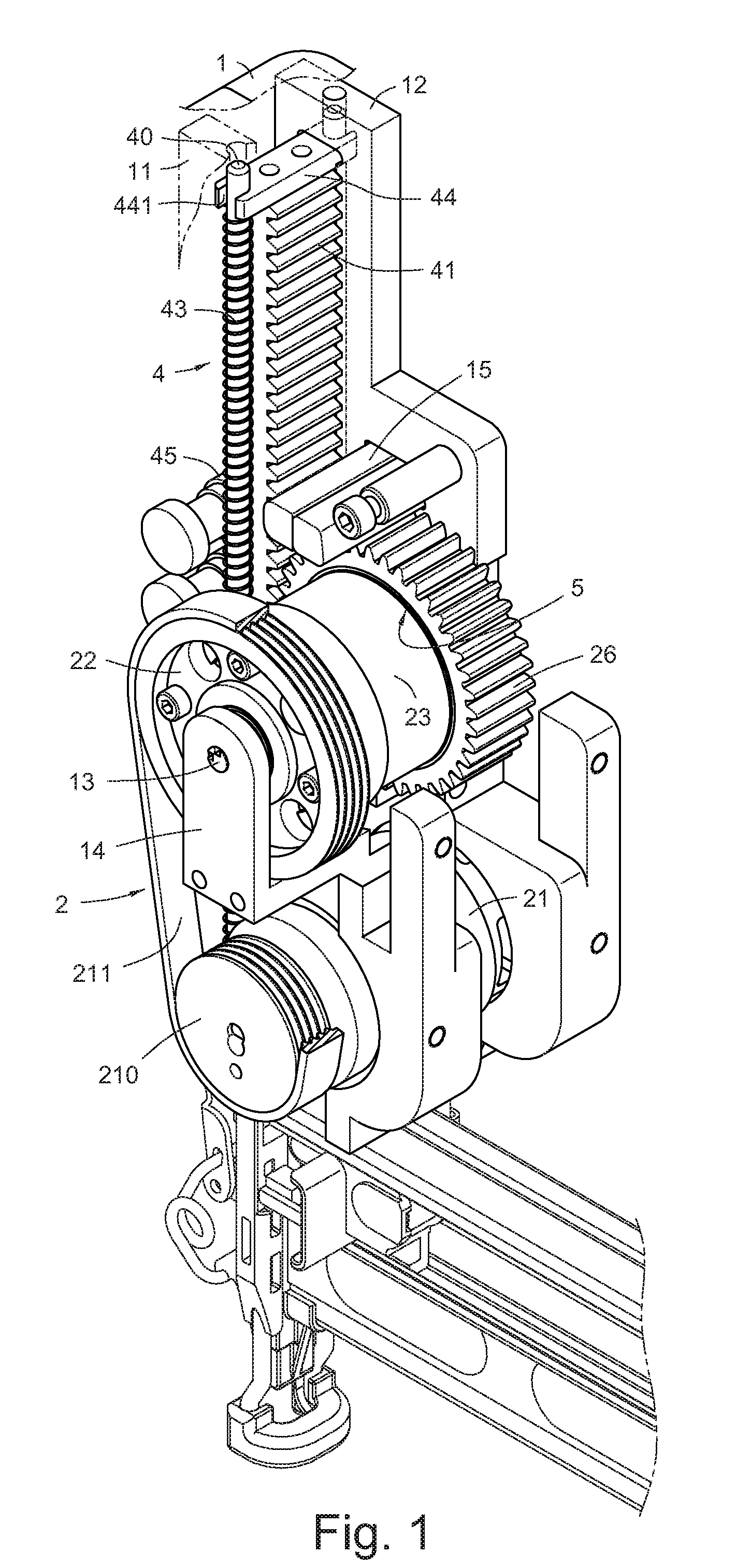
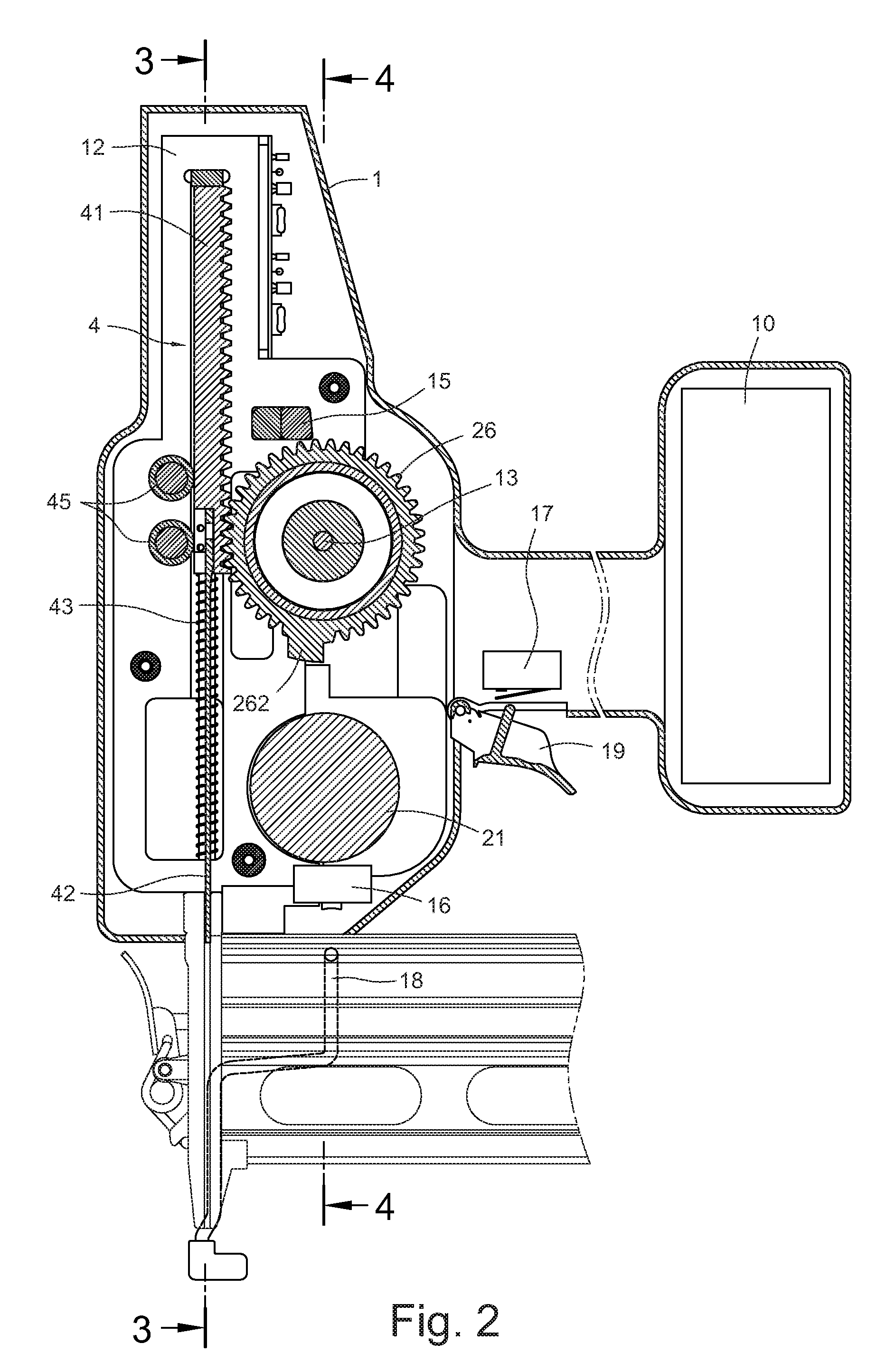
[0023]Referring to FIG. 1, a transmission mechanism for an electric nail gun in accordance with a first embodiment of the present invention is provided. A suitable power source, such as the battery pack 10 for providing direct current to the transmission mechanism, is received in a distal end of a housing 1. Two opposing supporting bracket 11, 12 are formed on a head portion of the housing 1 to mount a rotary transmission unit 2 and a linear transmission unit 4 thereon. A first switch 16 and a second switch 17 are formed on the housing 1. The first switch 16 is disposed on a bottom end of the housing 1 touchable by a safe sliding rod 18. The second switch 17 is located on an end side of the housing 1 touchable by a trigger 19 mounted on an end of the housing 1. The rotary transmission unit 2 has an electric driven driving wheel 26, preferably a driving gear.

[0024]In this embodiment, the linear transmission unit 4 has a rack 41 mounted by a spring in the nail gun 1 in mesh with the d...


PUM


Abstract

A transmission mechanism for an electric nail gun includes a linear transmission unit and a rotary transmission unit in a housing of the electric nail gun. The rotary transmission unit includes an electric driven driving wheel. The linear transmission unit includes a rack and a hitting bar. The hitting bar is disposed at a bottom of the linear transmission unit. The rack is in mesh with the driving wheel, slidably installed in the housing by a spring force, and configured to receive driving from the driving wheel and to drive the hitting bar to move linearly downward so as to hit a nail.

Description

BACKGROUND OF THE INVENTION[0001]1. Field of the Invention[0002]The present invention relates to a transmission mechanism for an electric nail gun, and more particularly to a transmission mechanism with a driving wheel driven by electricity disposed in a nail gun housing and a rack disposed in the nail gun housing and in mesh with the driving wheel, the driving wheel being configure for driving the rack to move downward linearly to hit a nail.[0003]2. Description of Related Art[0004]An electric nail gun is a type of tool used to drive nails into wood or some other kind of material. Usually, there is a battery pack or an AC electrical power source in a housing of the electric nail gun to provide electrical power to a motor, thereby rotating the motor. A rotary kinetic energy of the motor is transformed into a linear kinetic energy by a transmission mechanism to drive a hitting bar to hit a nail.[0005]Among a more advanced technology, many US patents, such as U.S. Pat. No. 6,607,111 a...

Claims


Application Information

Patent Timeline
IPC IPC(8): B25C1/06
CPCB25C1/06
Inventor LIANG, CHIA-SHENGCHANG, CHIN-LUNGTSENG, CHU HSIANG
Owner DE POAN PNEUMATIC
Why Eureka
Try Eureka