
Workpiece grasper and workpiece transfer apparatus using the same

a technology of workpiece transfer and workpiece, which is applied in the direction of electrical programme control, instruments, program control, etc., can solve the problems of inability to stop processing workpieces, inability to process workpieces, and increased time to stop facilities during workpiece transfer operations, so as to shorten the time to stop processing facilities, the effect of reducing the necessary operation

Inactive Publication Date: 2009-04-16
DENSO CORP
View PDF4 Cites 40 Cited by
  • Summary
  • Abstract
  • Description
  • Claims
  • Application Information

AI Technical Summary

Benefits of technology

[0008]The present embodiment has been made in consideration of the foregoing. It is therefore an object of the present embodiment to provide a workpiece grasper and a workpiece transfer apparatus using the workpiece grasper capable of shortening the time to stop a processing facility.
[0010]The two hands can grasp different workpieces at the same time. Further, one hand can grasp a workpiece while the other hand can place the workpiece. The one hand can grasp the workpiece from the processing facility and the other hand can place the grasped workpiece on the processing facility. It is thereby possible to shorten the time to stop the processing facility.
[0013]The base member is rotated to rotate the two hands above the line along the transfer direction of workpieces, making it possible to easily change the hands.
[0015]It should be noted that upon completion of the fifth process, the second processing facility is ready for operation. Compared to the transfer of workpieces using only one hand, the exemplary workpiece grasper described herein can decrease necessary operations and shorten the time to stop the processing facility.

Problems solved by technology

When a transfer robot such as is described in JP-2001-191278 A is used in a production line including two or more transfer processes such as transfers to processing facilities 1 through 3 or simply facilities 1 through 3, a known disadvantage is present involving an increase in the time to stop facilities during workpiece transfer operations.
Disadvantages arise in that during the transfer, the facility 2 needs to stop processing for mounting and dismounting of the workpieces.
That is, during the time when the hands travel from facility 2 to facility 3, facility 3 to facility 1, and from facility 1 back to facility 2, which further involves eight separate up and down movements of the arms, facility 2 must stop processing workpieces and is therefore disadvantageously idle.

Method used


Image

  • Workpiece grasper and workpiece transfer apparatus using the same
  • Workpiece grasper and workpiece transfer apparatus using the same
  • Workpiece grasper and workpiece transfer apparatus using the same

Examples


Embodiment Construction

[0115]Embodiments will be described in further detail with reference to the accompanying drawings.

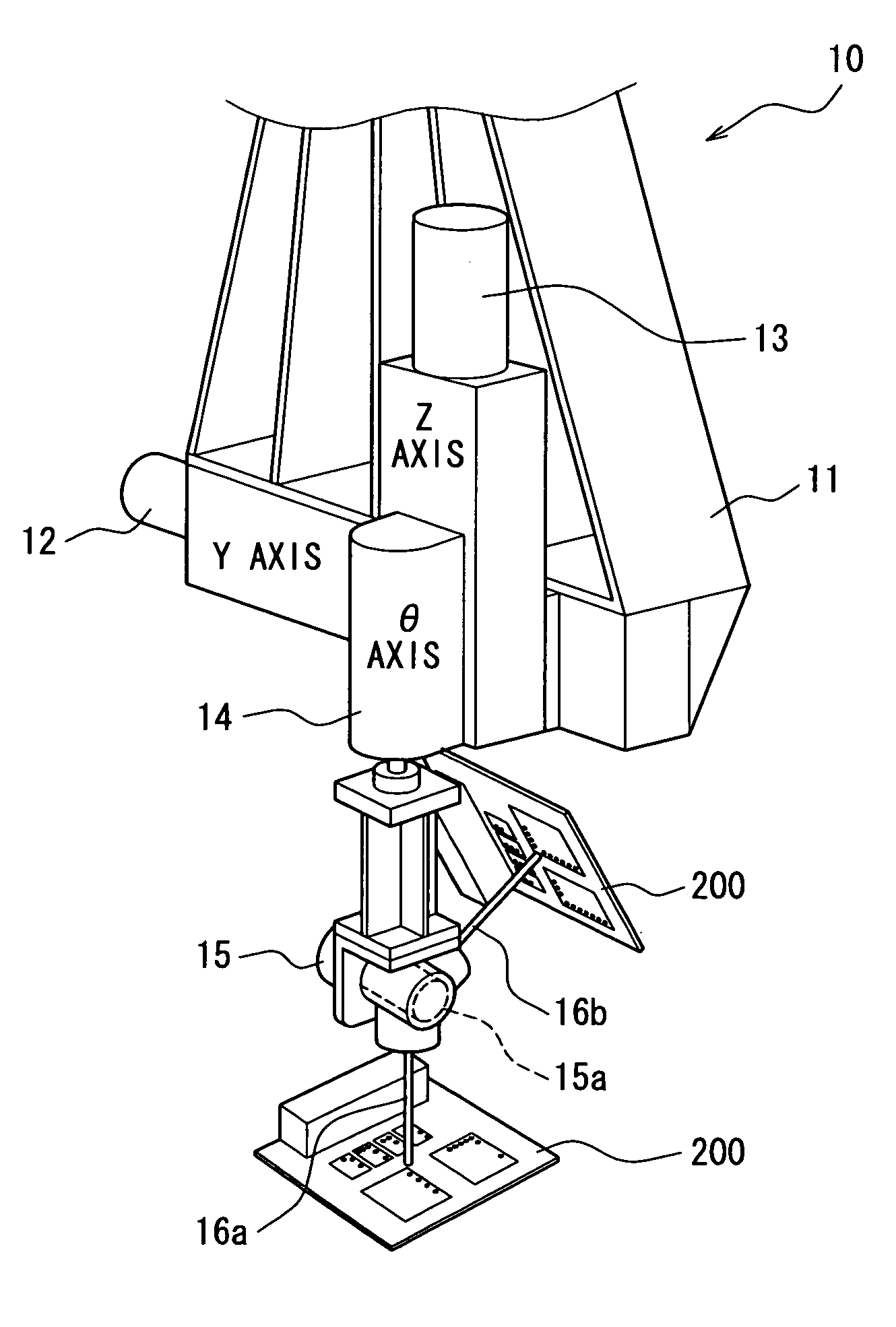
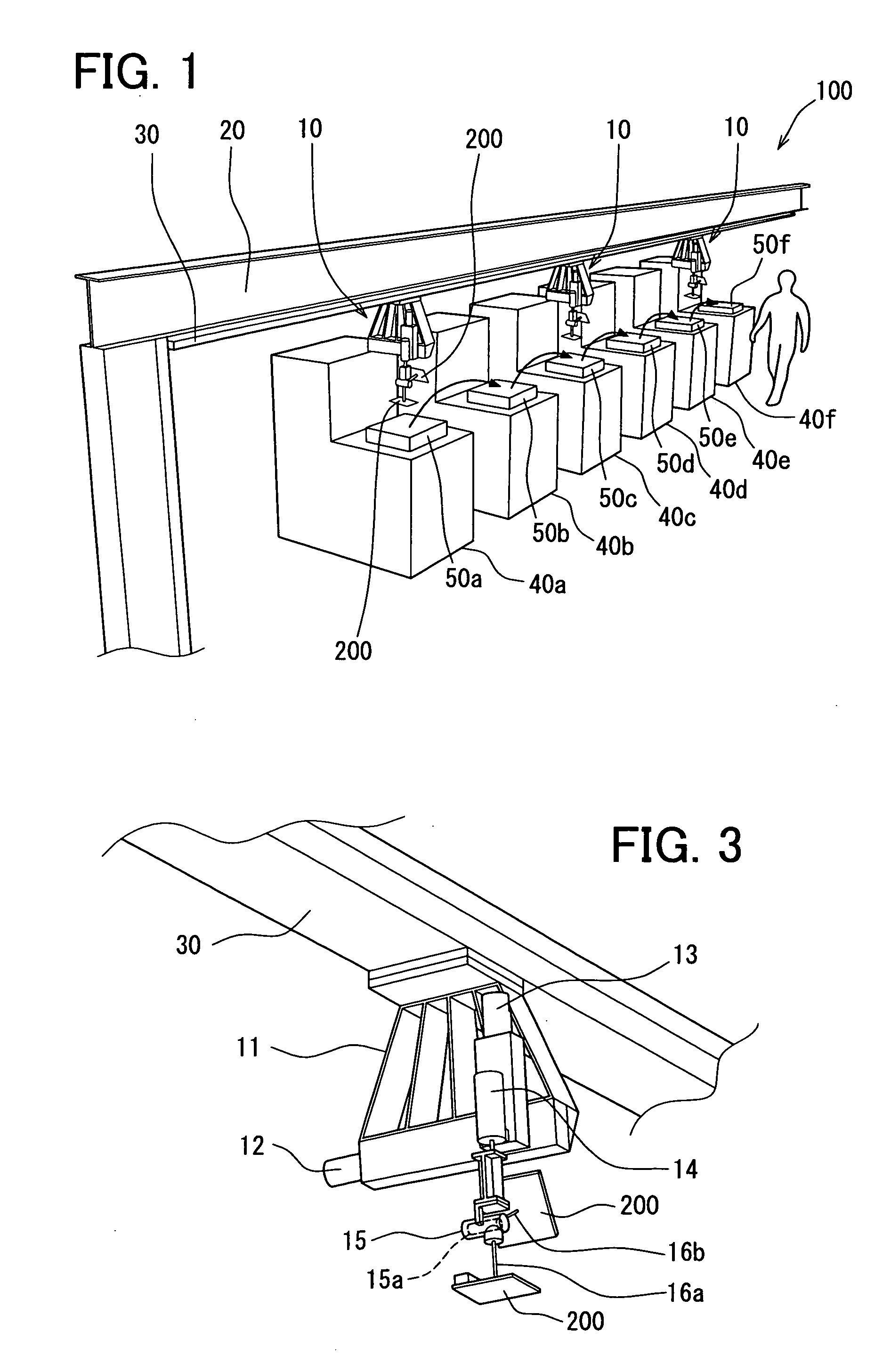
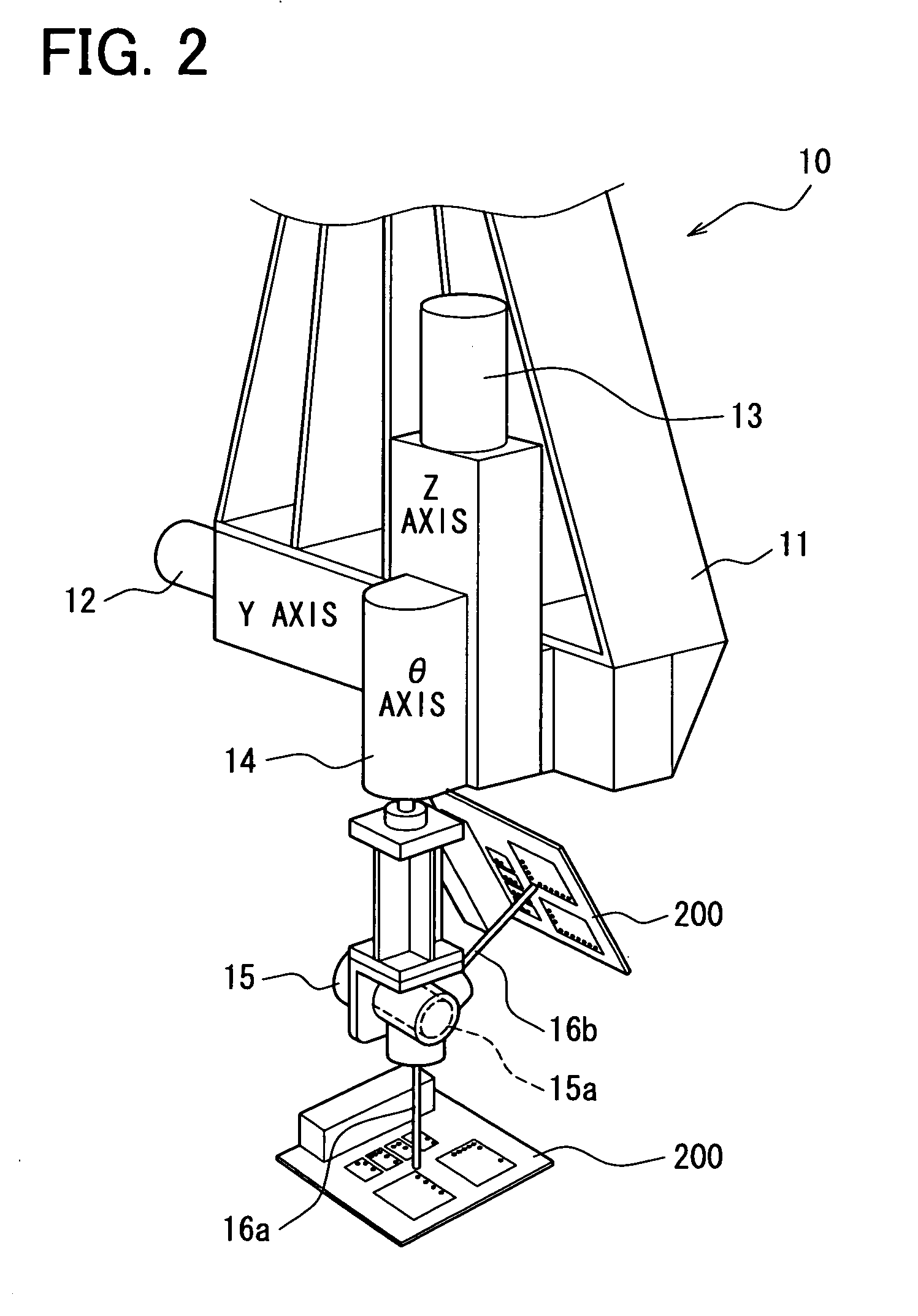
[0116]FIG. 1 through FIG. 5 show various aspects of an exemplary workpiece transfer apparatus in accordance with the present embodiment.

[0117]As shown in FIG. 1, the workpiece transfer apparatus includes a workpiece grasper 10 and is applied to a production line 100 that uses three or more processing facilities such as processing facilities 40a through 40f that are used to process a workpiece 200. The workpiece transfer apparatus automatically transfers the workpiece 200 including a printed board, printed wiring board, printed circuit board or the like, including a printed board mounted with circuit parts. The processing facilities 40a through 40f are used to process the workpiece 200.

[0118]The processing facilities 40a through 40f of the production line 100 correspond to individual processes of the workpiece 200. The workpiece transfer apparatus transfers the workpiece 200 to the proce...


PUM


Abstract

A workpiece grasper and a workpiece transfer apparatus shorten the time that a processing facility must be stopped. A workpiece is transferred along a production line and processed in three or more processing facilities. A workpiece grasper grasps and places the workpiece to be transferred between the processing facilities. The workpiece grasper includes a rotation mechanism and two hands capable of grasping and placing the workpiece. The rotation mechanism rotates the two hands above a line along a transfer direction of the workpiece. The rotation mechanism changes the hands for grasping the workpiece from a processing facility and changes the hands for placing the grasped workpiece on a processing facility.

Description

CROSS REFERENCE TO RELATED APPLICATIONS[0001]The present application is based on and claims priority to Japanese Patent Application No. 2007-264735, filed Oct. 10, 2007, the entire contents of which are incorporated herein by reference.BACKGROUND OF THE INVENTION[0002]1. Field of the Invention[0003]The present invention relates to a workpiece grasper and a workpiece transfer apparatus using the same applicable to a production line including two or more transfer processes.[0004]2. Description of the Related Art[0005]The conventional transfer robot described in JP-2001-191278 A provides an example of a workpiece grasper that includes first and second hands used grasps and transfers a workpiece.[0006]When a transfer robot such as is described in JP-2001-191278 A is used in a production line including two or more transfer processes such as transfers to processing facilities 1 through 3 or simply facilities 1 through 3, a known disadvantage is present involving an increase in the time to...

Claims


Application Information

Patent Timeline
IPC IPC(8): B25B1/20B65G65/00B64F5/00B23Q17/22B25J9/22
CPCB23Q41/02B23Q7/04B25J15/0052B25J9/1692
Inventor USUI, HIROKAZU
Owner DENSO CORP
Learn More