

Display apparatus, quantity-of-light adjusting method for display apparatus and electronic equipment
- Summary
- Abstract
- Description
- Claims
- Application Information
AI Technical Summary
Benefits of technology
Problems solved by technology
Method used
Image

Examples
Embodiment Construction
[0052]With reference to drawings, embodiments of the invention will be described.
[Layout in LED Back Light]
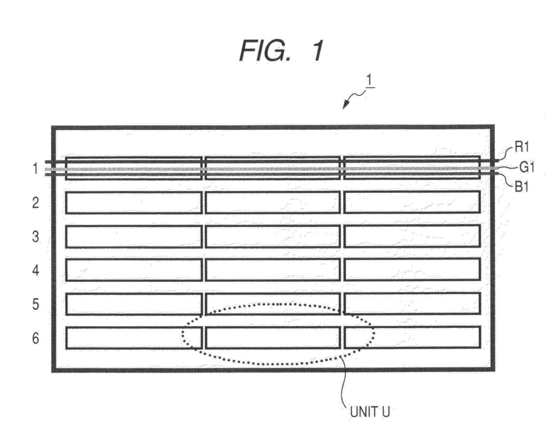
[0053]FIG. 1 is a schematic plan view illustrating the layout in an LED back light. An LED back light is placed at the back of display means (such as a liquid crystal panel) in a display apparatus 1 and supplies light to the display means. In the LED back light, one unit U has multiple R, G and B LEDs, and the units U are placed horizontally and vertically. As the area of the display means such as a liquid crystal panel increases, the number of units U disposed vertically and horizontally increases. However, one unit U may be provided for display means in a smaller area.
[Configuration of Unit]
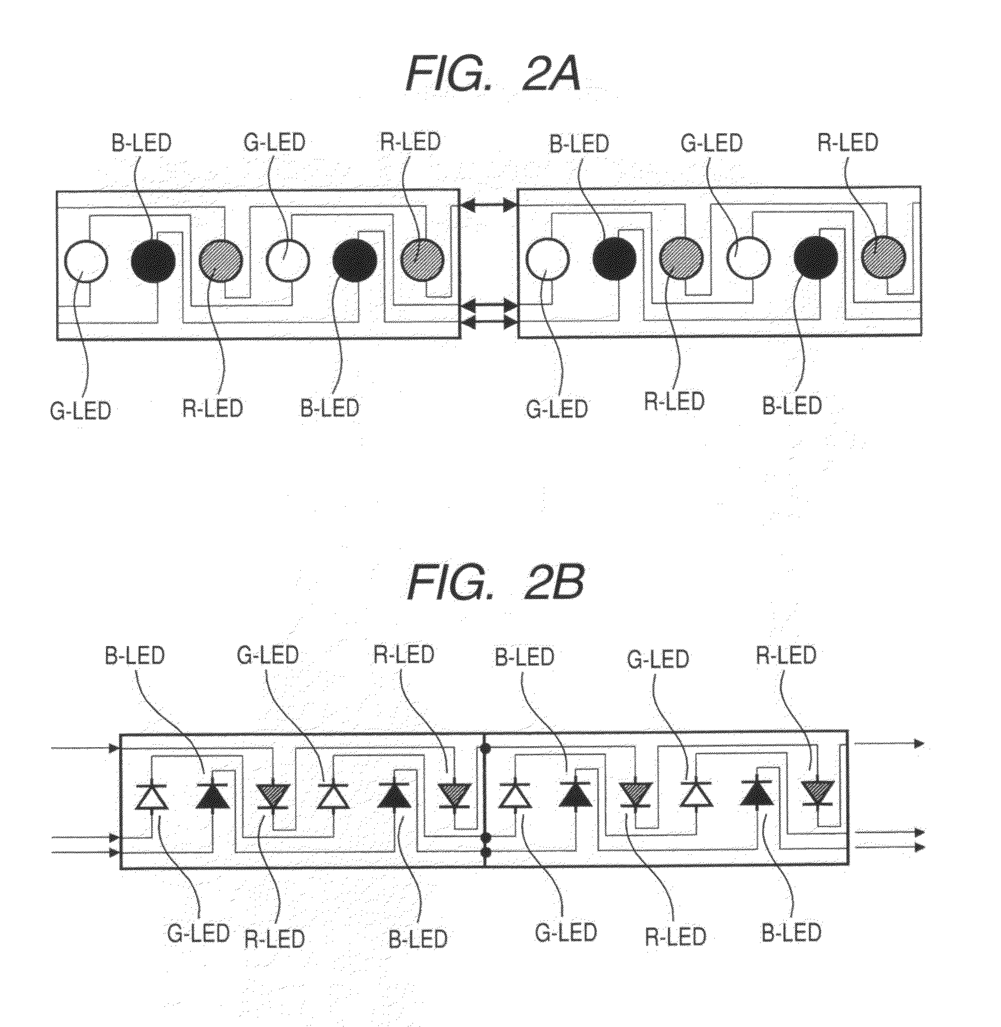
[0054]FIGS. 2A and 2B are schematic diagrams illustrating a configuration of an LED unit employed in an LED back light, and FIG. 2A is a layout diagram, and FIG. 2B is a circuit diagram. In one unit, R (red), G (green) and B (Blue) LEDs (or R-LED, G-LED and B-LED) are laid out in a predete...
PUM
 Abstract
Description
Claims
Application Information