Intelligent Camera Head

a camera head and intelligent technology, applied in the field of camera heads, can solve the problems of not being able to utilize new or different camera heads utilizing different timing signals, not being able to direct view of internal body cavities by medical personnel, and (built-in) solid-state imagers, etc., to achieve the effect of increasing the data carrying capacity of the cable connection, increasing the data carrying capacity, and increasing the cable length

Inactive Publication Date: 2009-04-16
KARL STORZ ENDOSCOPY AMERICA
View PDF27 Cites 12 Cited by
  • Summary
  • Abstract
  • Description
  • Claims
  • Application Information

AI Technical Summary

Benefits of technology

[0019]In a further advantageous embodiment a video imaging system is provided having a small diameter, lightweight, universal cable configuration, utilizing low-voltage differential signals (“LVDS”). Although various other signal methods may be used, LVDS based architecture is preferred due to its low power consumption, high-speed data transfer rate, two-wire unidirectional connectivity, and high resistance to internal (cross-talk) and external electromagnetic interference. The cable architecture is designed to reliably transmit and receive data from different camera heads to CCUs, as well as accommodate the differing technical requirements of different camera heads.
[0021]The architecture of the universal cable also greatly increases the data carrying capacity of the cable connection between the various CCUs and the varying camera heads. This need for increased data carrying capacity can be achieved by means of data multiplexing, while still maintaining the desired small diameter, and weight of a single cable. What is meant by “data multiplexing” is that any single signal path can be utilized for transmitting multiple data streams on a time-sharing basis. The new cable architecture will also allow for a greater cable length while not sacrificing data carrying capacity or inducing signal noise.
[0022]In a further advantageous embodiment a video imaging system is provided where the digital camera head comprises at least one processing device used to receive parallel digital video data and compress the data into a digital serial data stream for reception by at least one digital serial driver; and to receive digital serial data from at least one digital serial receiver. The programming flexibility realized using at least one processing device (such as, but not limited to, field programmable gate arrays, computer programmable logic devices, digital signal processors, and microprocessors) provides the necessary speed, precision, and adaptability desired for endoscopic video camera applications. Moreover, camera head physical size, production costs, and power consumption considerations are further mitigated by using a processor based video data compression and conversion configuration, instead of using discrete multiplexing devices. Additionally, as imager technologies improve, the invention can be easily adapted, by means of programming revision, to further exploit those improvements.

Problems solved by technology

Some special purpose endoscopes have integrated (built-in) solid-state imagers, which do not facilitate direct viewing of internal body cavities by medical personnel without an accompanying video imaging system and display.
Disadvantageously, only camera heads requiring timing signals matched to the CCUs timing generator may be utilized with this arrangement.
Therefore, new or differing camera heads utilizing different timing signals cannot be utilized.
Another disadvantage of known video imaging systems is that the various camera heads have differing cable structures based upon the camera head parameters.
However, a disadvantage of providing dedicated parallel wires is that typically twenty to thirty separate lines are required to control, energize and receive image data from camera heads, with most signal lines requiring a dedicated connector pin.
The larger this bundle becomes, the more likely it is to interfere with medical personnel's use of the video imaging system.
Moreover, utilizing dedicated parallel wire type cabling is undesired when additional functionality is required and added to either the camera head or CCU.
Another aspect of video imaging systems is that undesired image “noise” can be encountered, due to stray electromagnetic signals being induced upon the wires of the cable bundle (commonly referred to as electromagnetic interference, “EMI”), and from signal “cross-talk” within the cable itself.
These analog signals, especially image data, are very susceptible to EMI from surgical electro-cautery equipment and the like.
The use of EMI shielding is prohibitive due to the added cost and subsequent cable size and weight increase.
Moreover, the desired endoscopic camera head cable length itself (typically 10 feet or more) tends to induce noise as analog signals are propagated down its length.

Method used


Image

  • Intelligent Camera Head
  • Intelligent Camera Head
  • Intelligent Camera Head

Examples


Embodiment Construction

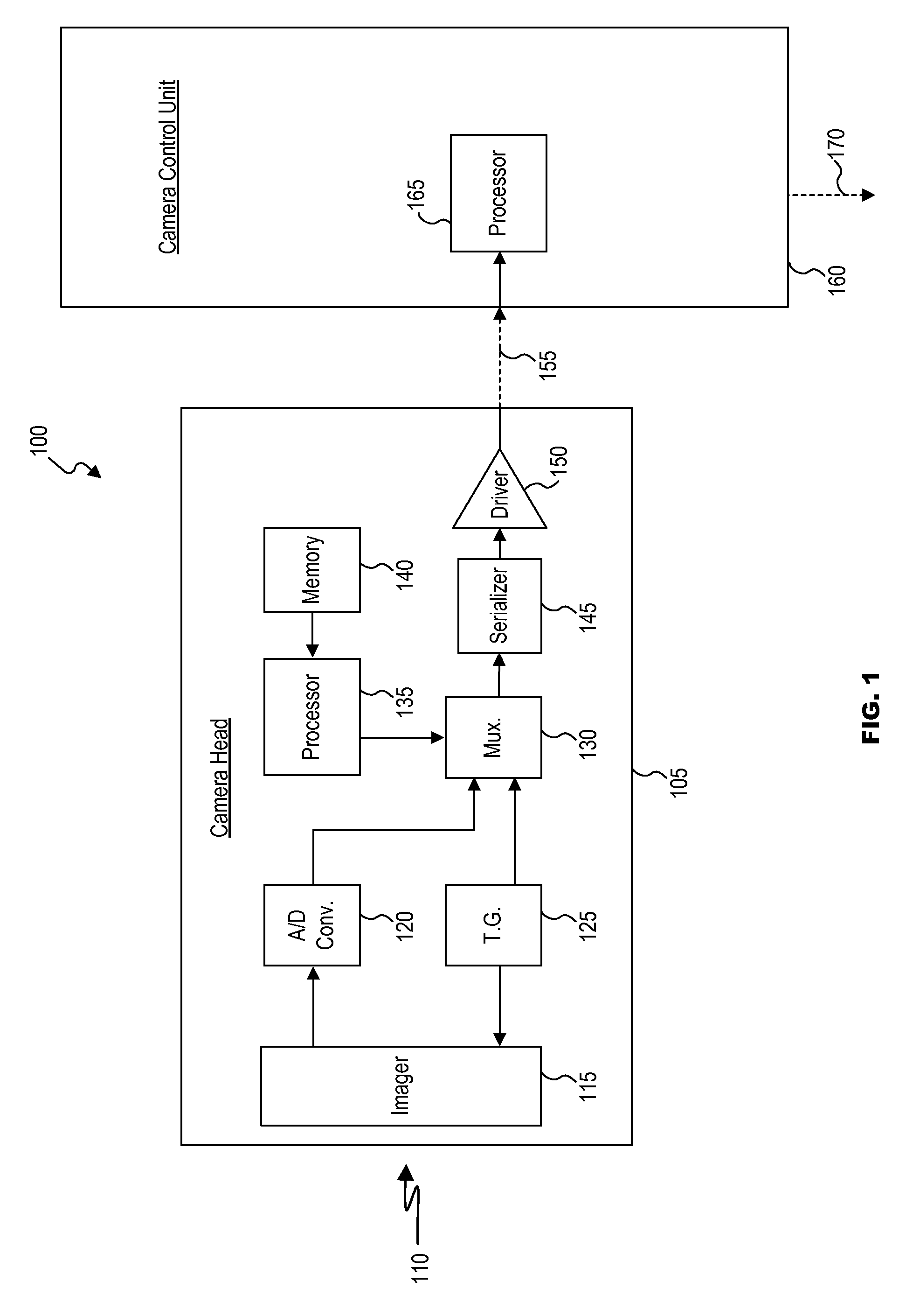
[0031]FIG. 1 illustrates an advantageous embodiment of the video imaging system 100. A camera head 105 is provided having an imager 115 for receiving photonic energy 110 reflected off a viewed object (not shown). The imager 115 utilizes timing signals generated in timing generator 125 to develop output analog image data corresponding to the received photonic energy 110. The imager 115 converts the received photonic energy 110 to output analog image data received by analog-to-digital converter 120. The analog-to-digital converter 120 in turn converts the received analog image data to digital image data. The digital image data is then fed into multiplexer 130. The timing generator 125 also provides an input to multiplexer 130. A processor 135, having access to a memory device 140 is also located in the camera head 105. The processor 135 may send camera information stored in memory device 140 to multiplexer 130. The multiplexer 130, multiplexes the various received input signals, gener...


PUM


Abstract

A video imaging system that minimizes the effect of EMI on the image data, provides a small, lightweight easy to use camera head, permitting interchangeable use of a variety of intelligent camera heads with a single camera control unit, and allows the utilization of new camera heads with new functions as they become available without having to replace the existing CCU.

Description

CROSS-REFERENCE TO RELATED APPLICATIONS[0001]The present application is a continuation of and claims priority from pending U.S. patent application Ser. No. 10 / 033,316, filed Dec. 28, 2001, the content of which is incorporated herein by reference.FIELD OF THE INVENTION[0002]The invention relates to a camera head having components permitting its interchangeable use with a variety of camera control units.BACKGROUND OF THE INVENTION[0003]The field of video endoscopy, to which the present invention generally relates, includes medical diagnostic and therapeutic disciplines that utilize endoscopes to penetrate and view otherwise inaccessible body cavities utilizing minimally invasive surgical procedures. Coupling of video imaging cameras (incorporating solid-state imagers) to endoscopes, for image reproduction, has become standard within the field. Endoscopic video cameras (hereinafter referred to as “camera heads”), are most advantageously small and lightweight for ease of use by medical ...

Claims


Application Information

Patent Timeline
Patent Type & Authority Applications(United States)
IPC IPC(8): H04N5/76H04N5/225H04N5/232
CPCA61B1/00059A61B1/042H04N5/23203H04N2005/2255H04N5/232H04N23/555H04N23/66H04N23/661H04N23/617H04N23/665
Inventor AMLING, MARC R.CHATENEVER, DAVID
Owner KARL STORZ ENDOSCOPY AMERICA
Why Eureka
Try Eureka