Holey fiber

a fiber and hole technology, applied in the field of hole fibers, can solve the problem that the dispersion of waveguides cannot be positiv

Inactive Publication Date: 2009-04-16
FURUKAWA ELECTRIC CO LTD
View PDF1 Cites 17 Cited by
  • Summary
  • Abstract
  • Description
  • Claims
  • Application Information

AI Technical Summary

Benefits of technology

[0010]The purpose of this present invention is to provide a holey fiber which has its zero-dispersion wavelength of less than 700 nm and acts as single mode at the zero-dispersion wavelength.

Problems solved by technology

However, ordinary silica-base optical fiber has negative material dispersion at the wavelength below 1270 nm and the waveguide dispersion cannot be positive.
Because of that, mode interference and / or modal dispersion is generated and it causes problem for applications which requires high dispersion control such as SC light source.

Method used


Image

  • Holey fiber
  • Holey fiber
  • Holey fiber

Examples


Embodiment Construction

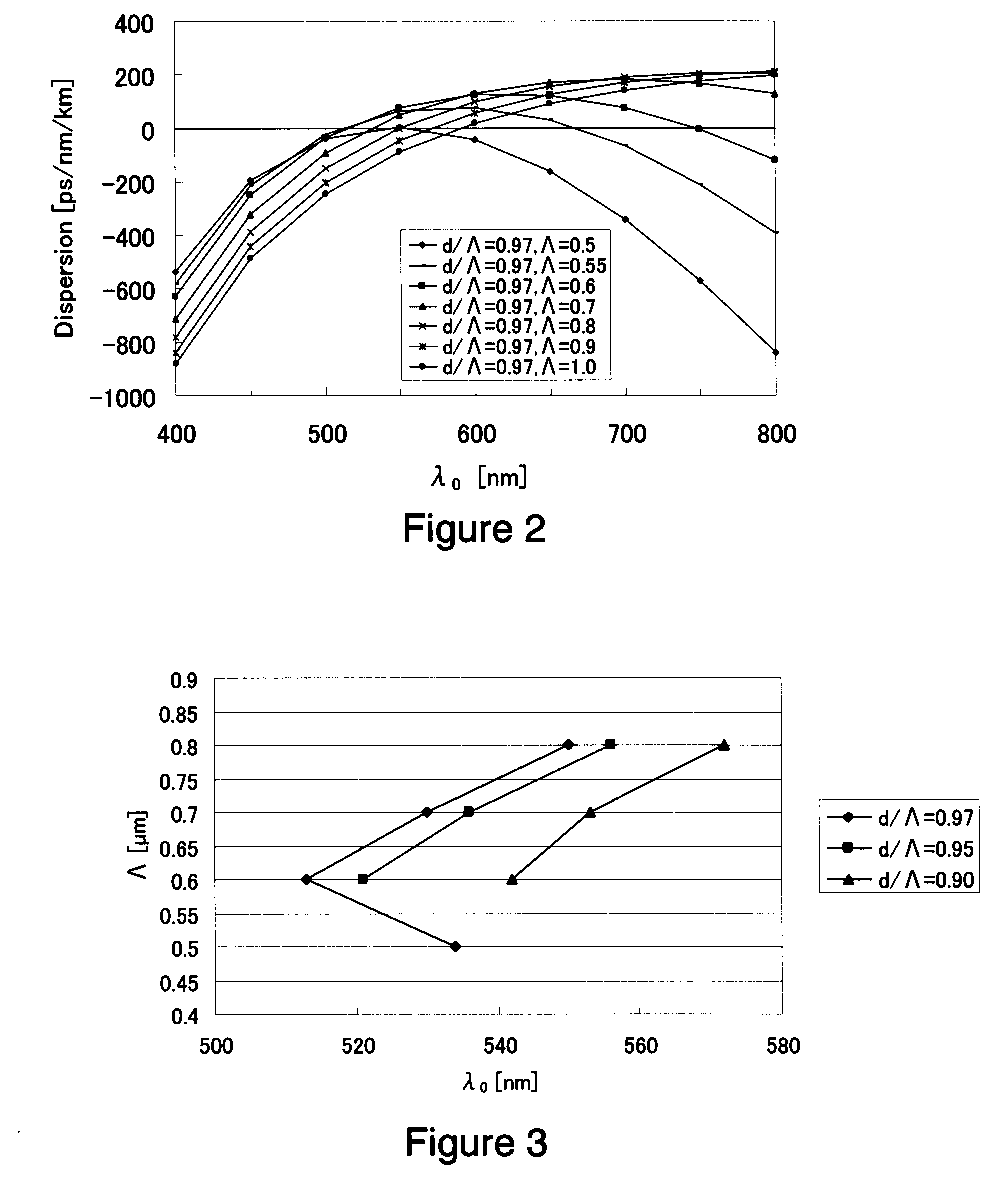
[0031]In the following, detailed description of embodiments of holey fibers according to the present invention is explained by referencing figures. While various embodiments of the present invention are described below, it should be understood that they are presented by way of example, and are not intend to limit the applications of the presented invention. Also, if terms are not defined in this specification, those terms are accordance with definitions and measuring method of International Telecommunication Union Telecommunication Standardization Sector (ITU-T) G.650.1.

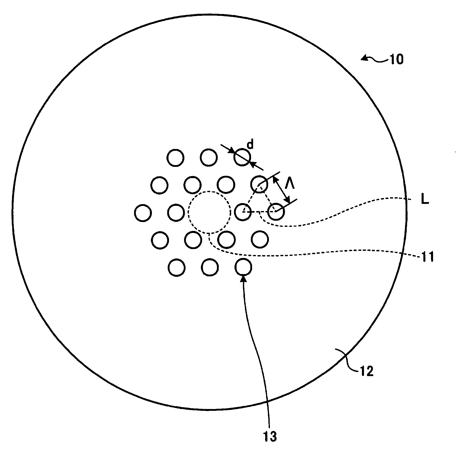
[0032]FIG. 1 is a schematic cross section of a holey fiber according to one of the embodiments of the present invention. As shown in FIG. 1, the holey fiber 10 has a core region 11 at the center of the fiber and a cladding region 12 formed at the circumference of the core region 11. The core region 11 and the cladding region 12 are both made from pure silica glass which is not doped with any dopants for controlling i...


PUM


Abstract

A holey fiber, which has a zero-dispersion wavelength of less than 700 nm and operates as single mode under its zero-dispersion wavelength, is provided. The holey fiber according to the present invention comprises a core region that is formed at a center of the holey fiber; and a cladding region, formed at the circumference of the core region, which has a plurality of holes distributed as triangle lattice around the core region; wherein the holey fiber has a fundamental mode of less than 700 nm, a higher order mode, and the fundamental mode and the higher order mode confinement losses of less than 0.1 dB/m and more than 10 dB/m, respectively, at the zero-dispersion wavelength.

Description

CROSS-REFERENCE TO RELATED APPLICATIONS [0001]This application claims the benefit of priority from Japanese Patent Application No. 2007-265663 filed Oct. 11, 2007, the entire contents of which is incorporated herein by reference.TECHNICAL FIELD [0002]The present invention relates to a holey fiber which has a core region that is formed at a center of the holey fiber; and a cladding region, formed at the circumference of the core region, which has a plurality of holes distributed as triangle lattice around the core region.BACKGROUND OF THE INVENTION [0003]A holey fiber or a photonic-crystal fiber is a new type of an optical fiber which has a core region at the center of the optical fiber and a cladding region formed at the circumference of the core region, which has plurality of holes distributed around the core region. The holes in the cladding lower the average refractive index and by using the principle of total reflection in light, the fiber propagates light in a core region. The ...

Claims


Application Information

Patent Timeline
Patent Type & Authority Applications(United States)
IPC IPC(8): G02B6/032
CPCG02B6/02214G02B6/02347G02B6/02328
Inventor IMAMURA, KATSUNORI
Owner FURUKAWA ELECTRIC CO LTD
Why Eureka
Try Eureka