Fluororesin tube and method for producing the same

a technology of fluororesin and fluororesin tubes, which is applied in the field of fluororesin tubes, can solve the problems of difficult to completely eliminate the level difference trace of the fixed image, and achieve the effects of enhancing the abrasion resistance of the fluororesin tube, excellent tensile strength, and excellent tensile strength

Inactive Publication Date: 2009-04-16
JAPAN GORE TEX INC
View PDF8 Cites 10 Cited by
  • Summary
  • Abstract
  • Description
  • Claims
  • Application Information

AI Technical Summary

Benefits of technology

[0007]To enhance abrasion resistance of a fluororesin tube, a fluororesin tube having an excellent tensile strength (for example, 80 N / mm2 or more) may be used. The fluororesin tube having an excellent tensile strength can be produced by using a fluororesin film having an excellent tensile strength. More specifically, for example, as shown in a schematic perspective view of FIG. 1, a fluororesin tube 30 can be produced by winding and laminating a fluororesin film 20 having an increased tensile strength on a core material 10, fixing a winding shape through heat fusion (heat fusing), and removing the core material 10. The present inventors have already filed an application with respect to a fluororesin tube 30 (Japanese Unexamined Patent Publication (Kokai) No. 2005-24931). A tensile strength of a fluororesin film 20 can also be increased by an expanding treatment (stretching or orienting treatment). Since it also becomes possible to reduce the wall thickness to 20 μm or less by the expanding treatment, the expanding treatment also contributes to achieving high image quality without inhibiting a function of an elastic layer of a fixing roll.

Problems solved by technology

Therefore, when higher image quality is required, level difference becomes a defect which cannot be neglected.
However, even if the wall thickness of the fluororesin film 20 is highly reduced, it was difficult to completely eliminate trace of level difference of the fixed image.

Method used


Image

  • Fluororesin tube and method for producing the same
  • Fluororesin tube and method for producing the same
  • Fluororesin tube and method for producing the same

Examples


production example 1

[0092]A PTFE fine powder [“Fluon CD123” manufactured by Asahi Glass Co., Ltd.] and a molding auxiliary agent were mixed and the resulting paste was extruded, rolled-down and then dried to remove the molding auxiliary agent, and thus a PTFE tape (unbaked tape) having a thickness of 0.16 mm and a width of 150 mm was produced. The PTFE tape (unbaked tape) thus obtained was first expanded at an expanding ratio of 26 times (2,500%) in the TD direction and then expanded at an expanding ratio of 25 times (2,400%) in the MD direction under the conditions of an expanding temperature of 300° C. and an expanding rate of 50% / sec. While holding on four sides, the expanded tape was heated (baked) at a temperature of 375° C. for 15 minutes to obtain an expanded porous PTFE film (porosity: 80%, thickness: 6.0 μm). The expanded porous PTFE film was supplied to a calender rolling device, and the film was pressed (collapsed) under the conditions of a roll temperature of 70° C., a surface pressure of 8...

production examples 2 to 3

[0093]In the same manner as in Production Example 1, except that the thickness of the PTFE tape (unbaked tape) is changed to 0.23 mm (Production Example 2) or 0.3 mm (Production Example 3), each PTFE film (fluororesin film 20) was obtained. Characteristics (porosity, thickness and tensile strength) of a PTFE film B obtained in Production Example 2 and a PTFE film C obtained in Production Example 3 are shown in Table 1 below.

[0094](II) Fluororesin Tube 30

[0095]A fluororesin tube 30 was produced in the following manner described in Working Examples 1 to 4 and Comparative Examples 1 to 3.

working example 1

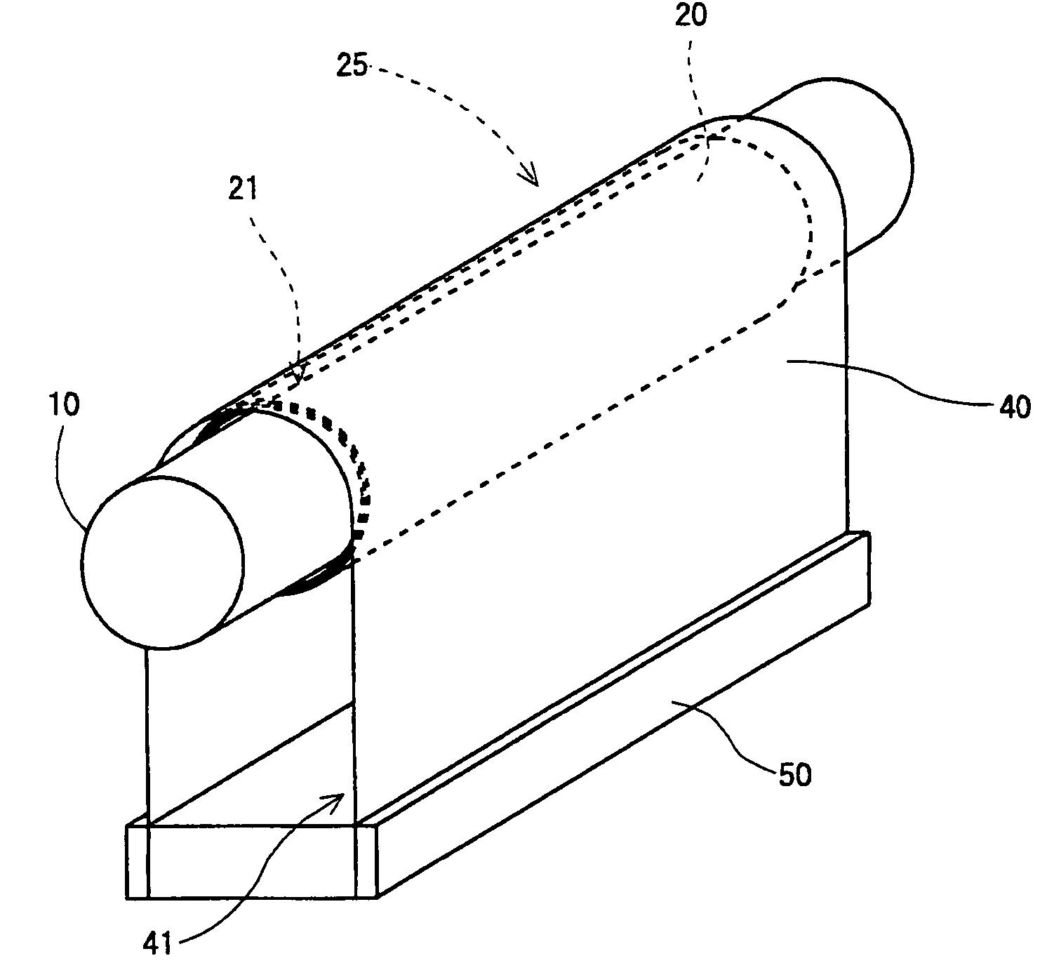
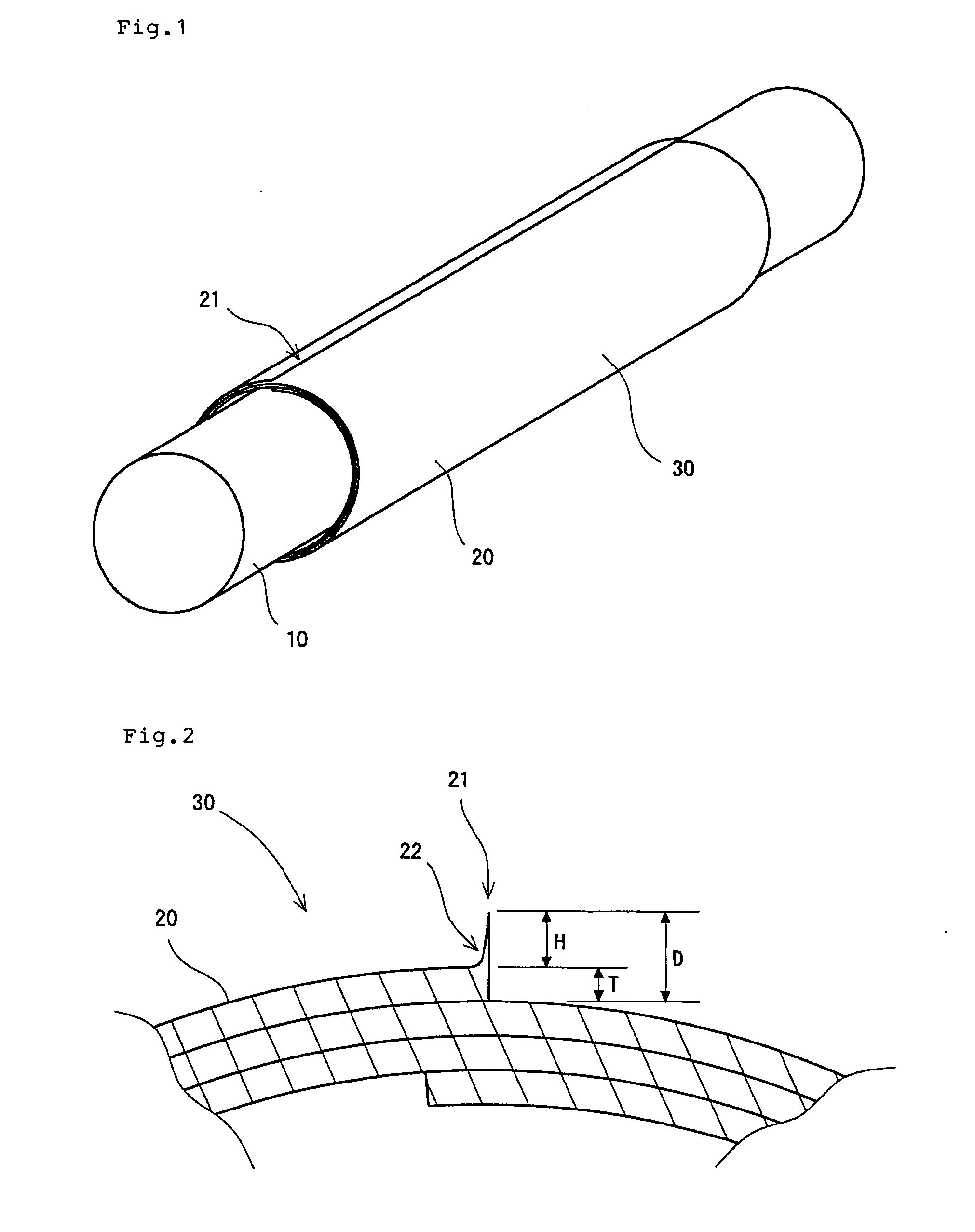
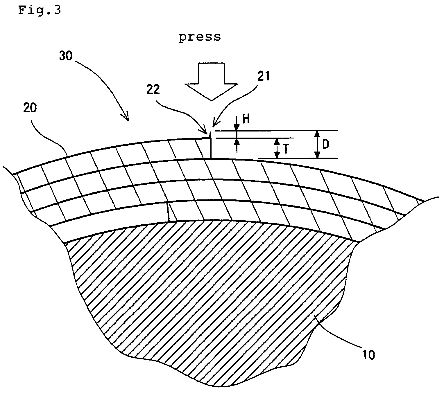
[0096]After subjecting one surface of the PTFE film A obtained in Production Example 1 to a corona discharge treatment (condition: 100 W / m2·min), the film was wound on a cylindrical shaped core material 10 (name of the core material: core material α, outer diameter: 25.9 mm, axial length: 540 mm) made of SUS304 so that the end-of-winding side 21 is parallel to an axial direction of a core material (core metal) 10 (approximately rolled sushi (vinegared rice rolled in dried layer)-shaped) as shown in FIG. 4. More specifically, the film was wound 9.1 times [a state where the film is wound 9 times (9-layered) and the 10th layer is only formed from a portion of film with a length of 0.1 times the circumferential length] while facing the surface subjected to the corona discharge treatment to inside and arranging the MD direction of the PTFE film A in the circumferential direction of the core material. And then the wound film was held on by attaching a ring-shaped stopper to both ends in t...


PUM

PropertyMeasurementUnit
thicknessaaaaaaaaaa
tensile strengthaaaaaaaaaa
heightaaaaaaaaaa

Abstract

A fluororesin tube 30 of the present invention has a tensile strength of 80 N/mm2 or more in both of the circumferential direction and the axial direction. The fluororesin tube 30 is produced by winding with two or more turn of a fluororesin film 20 having a thickness T of 2.5 μm or less (particularly 2.0 μm or less) to form a lamination. At least an outermost layer of the tube is fused to a layer immediately thereunder and a rising height H of the fluororesin film at the end-of-winding side 21 is always 0.1 μm or more and 2.0 μm or less when measured at any position of the side 21. A level difference D of the end-of-winding side 21 of the fluororesin tube is preferably more than or equal to sum of the film thickness T and 0.1 μm, and less than or equal to 3.0 μm (particularly 2.3 μm) when measured at any position of the side 21.

Description

TECHNICAL FIELD[0001]The present invention relates to a fluororesin tube which can be effectively utilized as components of an image fixing apparatus and the like, and a related art thereof.BACKGROUND ART[0002]In image fixing apparatuses such as an electrophotographic copier and a laser beam printer, an image (fixed image) is formed by a development step of depositing a toner on an electrostatic latent image formed on a photoconductor drum, thereby visualizing the electrostatic latent image; a transfer step of transferring the toner on a photoconductor drum onto a recording sheet (transfer material) such as paper to form a primary image; and a fixing step of treating the recording sheet on which the toner is deposited, using pressing and heating means [fixing members such as roll type pressing and heating means (fixing roll), belt type pressing and heating means for maintaining comparatively long fixing nip portion (fixing belt), etc.] thereby fixing the toner to the recording sheet...

Claims


Application Information

Patent Timeline
Patent Type & Authority Applications(United States)
IPC IPC(8): G03G15/20B32B1/08B32B5/18B32B37/00
CPCB29C53/562B29C53/60Y10T428/1376G03G15/2053Y10T428/1393B29K2027/18
Inventor OYAMA, SHINRO
Owner JAPAN GORE TEX INC
Why Eureka
Try Eureka