Elongate Flexible Torque Instruments And Methods Of Use

Inactive Publication Date: 2009-04-16
AORTX
View PDF99 Cites 177 Cited by
  • Summary
  • Abstract
  • Description
  • Claims
  • Application Information

AI Technical Summary

Problems solved by technology

Typical elongate flexible instruments may be comprised of flexible shafts, tubes, rods, etc., which may be susceptible to torque deflection or torque lag to the extent that rotation of one end of the instrument may not correlate closely to rotation of the opposite end of the instrument and substantial amount of wind-up or e

Method used


Image

  • Elongate Flexible Torque Instruments And Methods Of Use
  • Elongate Flexible Torque Instruments And Methods Of Use
  • Elongate Flexible Torque Instruments And Methods Of Use

Examples


Embodiment Construction

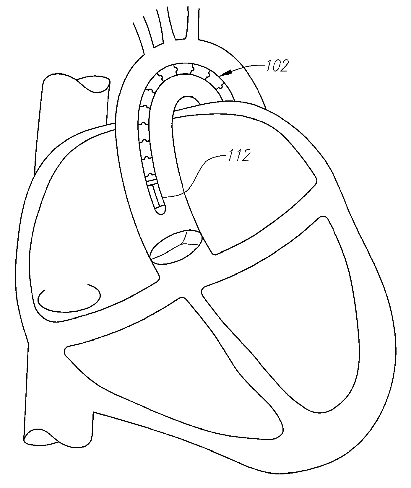
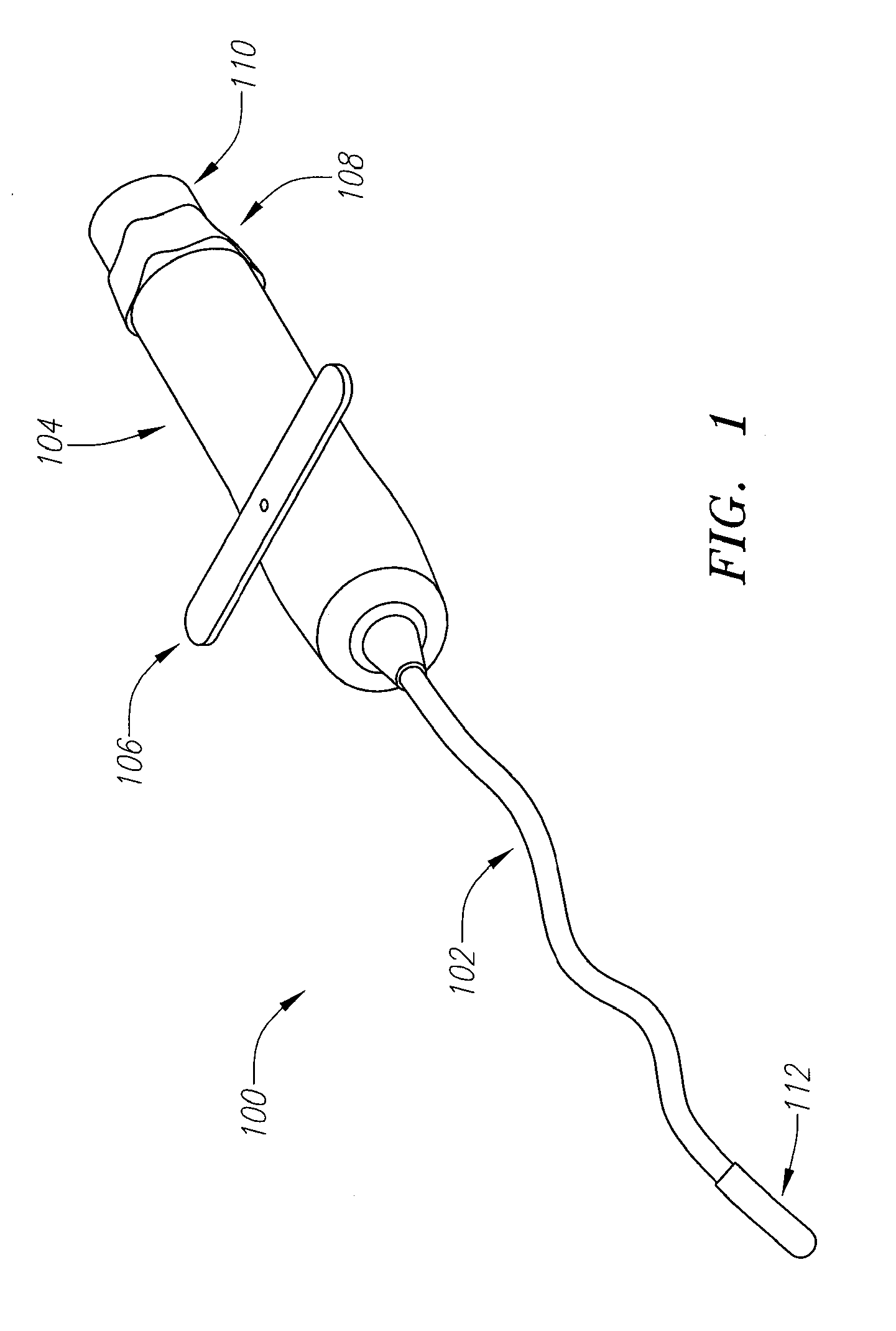
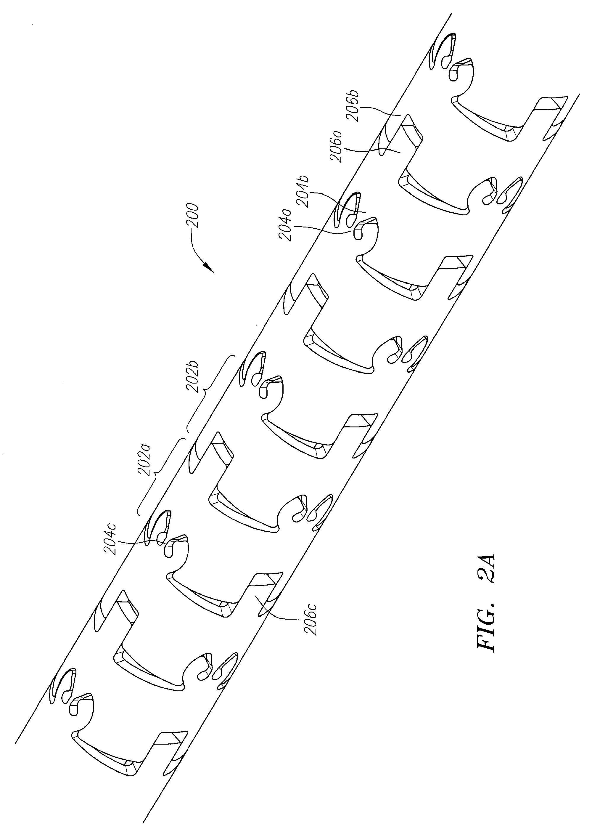
[0034]Elongate flexible torque instruments and methods for their use and manufacture are described herein. The elongate flexible torque instruments in accordance with embodiments of the present invention may be both flexible and stiff at the same time. In one embodiment, the elongate flexible torque instruments according to the present invention are designed and manufactured to be substantially flexible for pivoting, steering, bending, etc., but substantially stiff in resisting rotation and axial compression or extension such that they may effectively transmit rotation or torque and axial forces, loads, movements, etc., while it may be pushed, pulled, advanced, retracted, navigated, steered, bent, twisted, or contorted into various positions, shapes, orientations, and / or tight curvatures along tortuous pathways. The functional characteristics of the elongate flexible torque instruments as described herein are particularly suited as extension tools for deployment, placement, installa...


PUM


Abstract

Torque shafts and other related systems and methods are described herein. In one embodiment, the torque shafts are both flexible and capable of transmitting torque. An apparatus for transmission of torque includes an elongate body, comprising a plurality of joint segments, each joint segment configured to pivot with respect to an adjacent segment and being further configured to have at least two link elements.

Description

CROSS-REFERENCE TO RELATED APPLICATIONS[0001]This application is a continuation-in-part of PCT Application Serial No. PCT / US2007 / 071535, titled “Torque Shaft and Torque Drive”, filed on Jun. 19, 2007, which claims priority to U.S. Provisional Application Ser. No. 60 / 805,334, titled “Torque Shaft and Torque Drive”, filed on Jun. 20, 2006, each of which is incorporated herein by reference in its entirety for all purposes.BACKGROUND OF THE INVENTION[0002]1. Field[0003]Embodiments of the present invention relate generally to elongate flexible instruments, and more particularly, to the manufacture and use of such elongate flexible instruments, which may be configured to be extension tools for a variety deployment, placement, installation, maintenance, repair, or removal type of functions, procedures, operations, or applications.[0004]2. Background[0005]Typical elongate flexible instruments may be comprised of flexible shafts, tubes, rods, etc., which may be susceptible to torque deflecti...

Claims


Application Information

Patent Timeline
IPC IPC(8): A61B17/00
CPCA61F2/2427A61M25/0138A61M25/0147F16C1/04Y10T403/7073A61M25/0043A61M25/0113Y10T403/7045Y10T403/70F16C2226/78F16C2316/10
Inventor FORSTER, DAVID C.ROTH, ALEX T.BECKEY, BRIANWALSH, BRANDON G.HENEVELD, SCOTT
Owner AORTX
Why Eureka
Try Eureka