
Parking brake control system

a brake control and brake technology, applied in the direction of brake cylinders, anti-theft devices, instruments, etc., can solve the problems of affecting the precise control of the releasing operation, the control error may become larger, and the releasing operation may not be sufficiently carried out, so as to prevent the extension of the brake cable

Active Publication Date: 2009-04-16
ADVICS CO LTD
View PDF19 Cites 36 Cited by
  • Summary
  • Abstract
  • Description
  • Claims
  • Application Information

AI Technical Summary

Benefits of technology

[0010]The present invention is, therefore, made in view of the foregoing problem, and has an object to provide a parking brake control system for a vehicle, according to which a partial braking condition caused by, for example, the elongation of the brake cable is prevented.

Problems solved by technology

However, in such a control, a control error may become larger, as a result of being influenced by elongation of the brake cable.
However, in such a control, although the elongation of the brake cable is taken into consideration, the releasing operation may not be sufficiently carried out when the parking brake is maintained in the locked condition for a long period.
In other words, when the elongation of the brake cable may become larger than that estimated during such a longer period, such elongation may affect the precise control for the releasing operation.
Then, the control error may happen to occur.
When the control error may occur, a partial braking condition may be continued as a result of insufficient releasing operation.
Namely, it is a problem that a braking force is still generated even when the locked condition of the parking brake (the locked condition of the EPB system) has been released.

Method used


Image

  • Parking brake control system
  • Parking brake control system
  • Parking brake control system

Examples


first embodiment

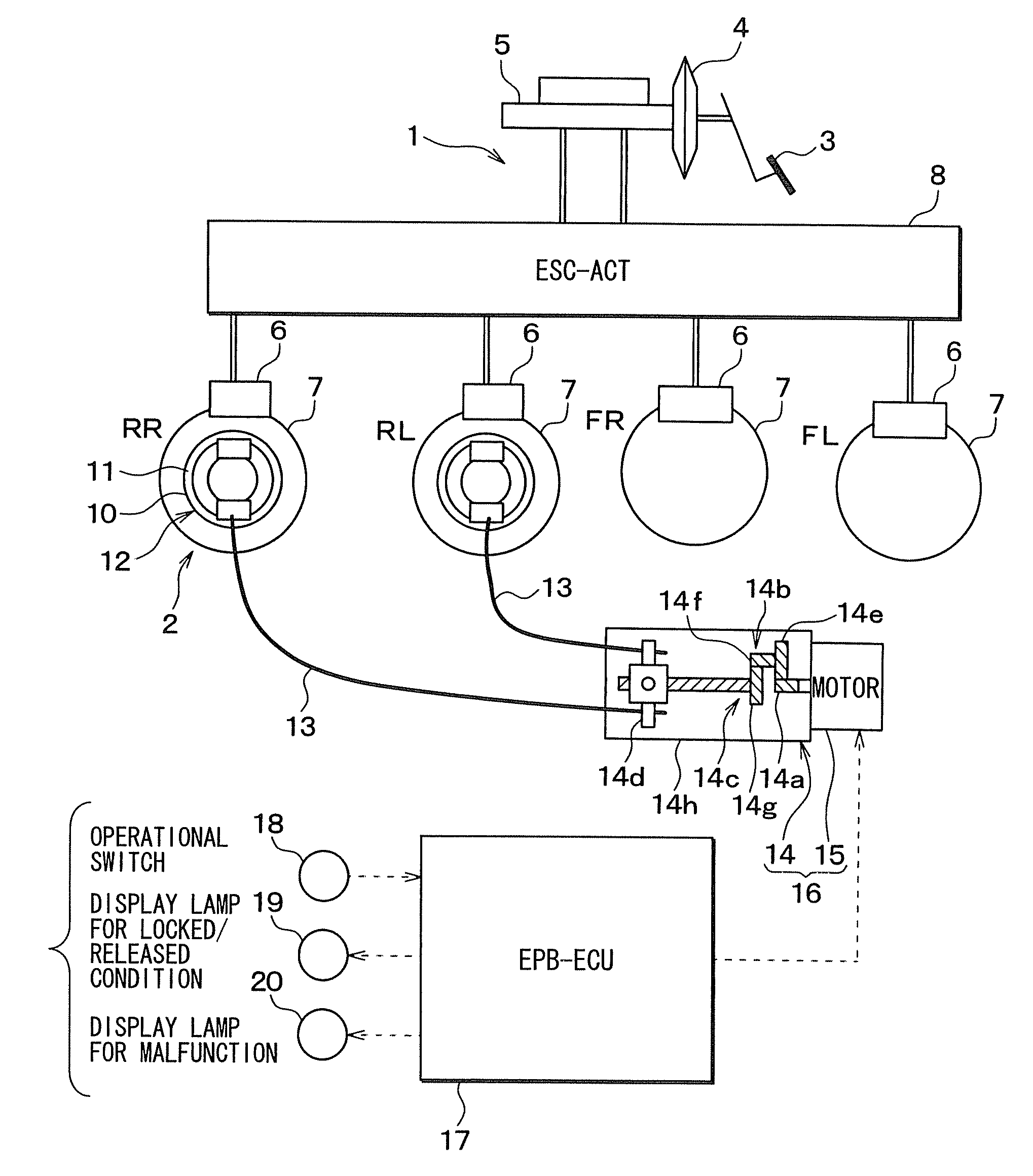
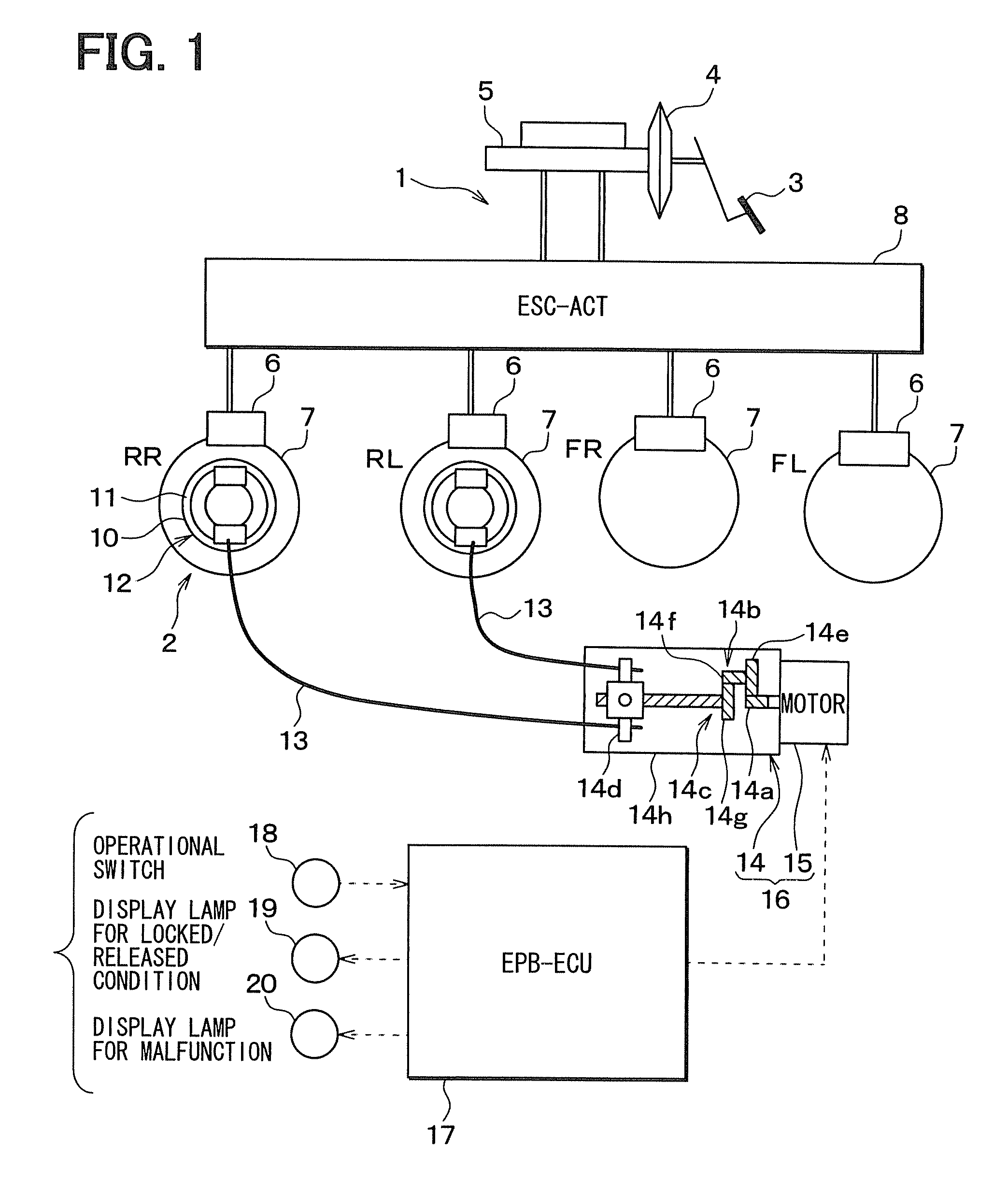
[0037]A first embodiment of the present invention will be hereinafter explained with reference to the drawings. FIG. 1 is a schematic view showing an entire structure of a brake system for a vehicle, to which a parking brake control system according to a first embodiment of the present invention is applied.

[0038]As shown in FIG. 1, a brake system has an ordinary brake system 1 for generating braking force depending on a brake pedal operation by a vehicle driver and an electronic parking brake (EPB) system 2 for restricting a vehicle movement during its parking condition.

[0039]In the ordinary brake system 1, a pedal stepping force applied to a brake pedal 3 by the vehicle driver is correspondingly increased by a brake booster 4, so that a brake fluid pressure is generated in a master cylinder 5 depending on the increased pedal stepping force. The brake fluid pressure is applied to wheel cylinders 6 of respective vehicle wheels to generate braking force. More exactly, when the brake f...

second embodiment

[0106]A second embodiment of the present invention will be explained. The second embodiment differs from the first embodiment in that the threshold values for various determinations are made as variable. The other points are the same to those of the first embodiment and the explanation thereof is omitted.

[0107]According to the embodiment, a step for calculating the threshold values is added to the process for the releasing (un-locking) operation of FIG. 7 of the first embodiment. FIG. 10 is a flow-chart showing a process for a parking brake releasing (un-locking) operation, which is used instead of the flow-chart of FIG. 7.

[0108]As shown in FIG. 10, a step 460 is inserted between the steps 400 and 410, and the calculation for the threshold values are done at the step 460. FIG. 11 is a flow-chart showing a process for calculating the threshold values. And FIGS. 12A to 12D are maps to be used for the calculation of the threshold values.

[0109]When the step 460 of FIG. 10 for calculatin...

third embodiment

[0117]A third embodiment of the present invention will be explained. The third embodiment differs from the second embodiment in that the manner for calculating the threshold values is so changed that the threshold values are changed depending on the differentiated value of the motor current. The other points are the same to those of the second embodiment and the explanation thereof is omitted.

[0118]According to the third embodiment, the process for releasing operation is carried out in accordance with the flow-chart of FIG. 10. However, the step 460 of FIG. 10 is carried out in a different manner from the second embodiment. FIG. 13 is a flow-chart showing the process for calculating the threshold values, which is carried out instead of the flow-chart of FIG. 11. And FIGS. 14A to 14C are maps to be used for the calculation of the above threshold values.

[0119]When the step 460 of FIG. 10 for calculating the threshold values is started, the EPB-ECU 17 determines at a step 700 of FIG. 1...


PUM


Abstract

A motor current detecting device is provided in a parking brake control system for detecting electric current flowing through an electric motor. And current supply to the electric motor is stopped in case of carrying out a parking brake releasing operation, when a time period in which a differentiated value of the electric current flowing through the electric motor is smaller than a predetermined threshold value exceeds a predetermined time. As a result, a partial braking condition, in which parking brake force partly remains even after the parking brake releasing operation, and which is caused by, for example, the elongation of the brake cable is prevented.

Description

CROSS REFERENCE TO RELATED APPLICATION[0001]This application is based on Japanese Patent Application No. 2007-264478 filed on Oct. 10, 2007, the disclosure of which is incorporated herein by reference.FIELD OF THE INVENTION[0002]The present invention relates to a parking brake control system for a vehicle, which controls a locking operation and a releasing operation of an electronic parking brake (hereinafter also referred to as EPB).BACKGROUND OF THE INVENTION[0003]A parking brake system is installed in a vehicle for restricting a vehicle movement during its parking condition. There is a manually operated parking brake system, according to which an operational force is transmitted to a brake device by pulling a brake cable by means of a brake lever. There is an electrically operated parking brake system, according to which a rotational force of an electric motor is transmitted to the brake device by pulling the brake cable by use of the electric motor.[0004]According to an electron...

Claims


Application Information

Patent Timeline
IPC IPC(8): B60T7/02F16D65/28
CPCB60T13/746B60T13/662B60T8/32
Inventor WATANABE, TAKASHIKONDO, KAZUMA
Owner ADVICS CO LTD
Learn More