Pneumatic tire

a pneumatic tire and tire body technology, applied in the field of pneumatic tires, can solve the problems of reducing the durability and wear resistance of the tread part, and the wear resistance may be reduced, so as to reduce the energy loss, reduce the amount of tire distortion, and narrow the crossing width of the belt layer

Active Publication Date: 2009-04-23
BRIDGESTONE CORP
View PDF13 Cites 2 Cited by
  • Summary
  • Abstract
  • Description
  • Claims
  • Application Information

AI Technical Summary

Benefits of technology

[0016]A sixth aspect of the present invention is that when, in the cross section: a straight line extending parallel with the line segment SW through the bead toes is set to be a straight line M; and a line segment on the tire equator line extending, parallel with the tire equator line, from the tread surface to the straight line M, is set to be a line segment SH, the length of the line segment extending, parallel with the tire equator line, from each point Q to the straight line M is 55% or less of the length of the line segment SH. With the aspect, it is possible to prevent the sidewall parts from contacting a road surface in a large rudder angle range, since the length of the line segment extending, parallel with the tire equator line, from the point Q to the straight line M is 55% or less of the length of the line segment SH.
[0017]A seventh aspect of the present invention is that when, in the cross section: positions on the line segment SW, with a length of 80% of the line segment SW in between, and taking the tire equator line as the center in between, are set to be a point K; and a line segment, extending on the tire equator line, parallel with the tire equator line, from the tread surface to the straight line M, is set to be a line segment SH, the length of the line segment extending, through the points K, in parallel with the tire equator line, from the tread surface to the straight line M, is 85% or less of the length of the line segment SH. With the aspect, since the length of the line segment extending through the points K, in parallel with the tire equator line, from the tread surface to the straight line M, is 85% or less of the length of the line segment SH, it is possible to set the position of the vicinities of the ends of the tread part on the inner side in the radial direction of the tire than the conventional tire, so that it is possible to narrow the cord crossing width of the belt layer. Consequently, since the deformation of the shoulder part is largely deformed, and the amount of distortion of the tire is increased, compared with the conventional tire, it is possible to reduce the energy loss due to deformation caused by the shear deformation in the tire circumference direction in the vicinity of the tire equator line of the tread part, thereby to reduce the rolling resistance.
[0018]An eighth aspect of the present invention is that, in the cross section, the outer contour line of the tire and the inner contour line of the tire in a region from the tire equator line to the point B are approximately parallel with the line segment SW. A ninth aspect of the present invention is that, a difference in length in the radial direction of the tire between the position where the length in the radial direction of the tire is longest and the position where the length in the radial direction of the tire is shortest is 50% or less of the length from the shortest belt layer to the tread surface on the tire equator line, in an upper region which is a region between the contours of the tire outer and inner rims in the cross section. When the inner surface of the pneumatic tire is round, the contact shape is one where only the vicinity of the tire equator line of the tread part contacts a road surface. Accordingly, wear in the vicinity of the tire equator line of the tread part results in being increased compared to the vicinities of the ends of the tread part. Hence, the outer contour line of the tire and the inner contour line of the tire are made to be approximately parallel with the line segment SW, and the difference in length in the radial direction of the tire in the upper region between the position where the length in the radial direction of the tire is longest and the position where the length in the radial direction of the tire is shortest is set to be 50% or less of the length from the shortest belt layer to the tread surface on the tire equator line. In this manner, the inner surface of the pneumatic tire is made to be flat, and the contact shape is thus optimized. Hence, it is possible to make the wear in the tread part uniform.
[0019]A tenth aspect of the present invention is that the pneumatic tire further includes reinforcing layers each of which extends, in the cross section, to the vicinity of the line segment SW, from a position in the inner side in the tire width direction than an edge of the one longest one, in length in the tire width direction, of the belt layers, and each of which is disposed on the inner side in the radial direction of the tire than one of the belt layers on the innermost side in the radial direction of the tire. With this aspect, since the reinforcing layer which extends, in the cross section, to the vicinity of the line segment SW, from a position in the inner side in the tire width direction than an edge of the longest one, in length in the tire width direction, of the belt layers, and which is disposed on the inner side in the radial direction of the tire than one of the belt layers on the innermost side in the radial direction of the tire, is further included, it is possible to make it difficult for the tire to be punctured even if the shoulder part runs on a nail the like. Additionally, it is possible to sufficiently secure the stiffness of the shoulder part, even if the shoulder part in a large rudder angle range and the like contact a road surface.
[0020]An eleventh aspect of the present invention is that when, in the cross section: an acute angle at which the cords forming the longest one, in length in the tire width direction, of the belt layers incline in relation to the tire equator line, is set to be an angle θ1; and an acute angle at which the cords forming the shortest belt layer incline in relation to the tire equator line is set to be an angle θ2, the angle θ1 is larger than the angle θ2. With this aspect, since, as described above, the cord crossing width of the belt layer is narrow, and the angle θ1 is larger than the angle θ2, the belt tension is focused on the vicinity of the tire equator line of the tread part. Hence, it is possible to improve the bending stiffness in the tire circumference direction in the vicinity of the tire equator line of the tread part, thereby to suppress deformation in the tire circumference direction in the vicinity of the tire equator line of the tread part.

Problems solved by technology

However, when the method by reducing the tan δ of rubber used for a tread part is employed, a problem arises that the wear resistance may be reduced.
In addition, when the method by making a gauge of a tread part shallow to the limit is employed, a problem arises that the durability and wear resistance of a tread part may be reduced.

Method used


Image

  • Pneumatic tire
  • Pneumatic tire
  • Pneumatic tire

Examples


first embodiment

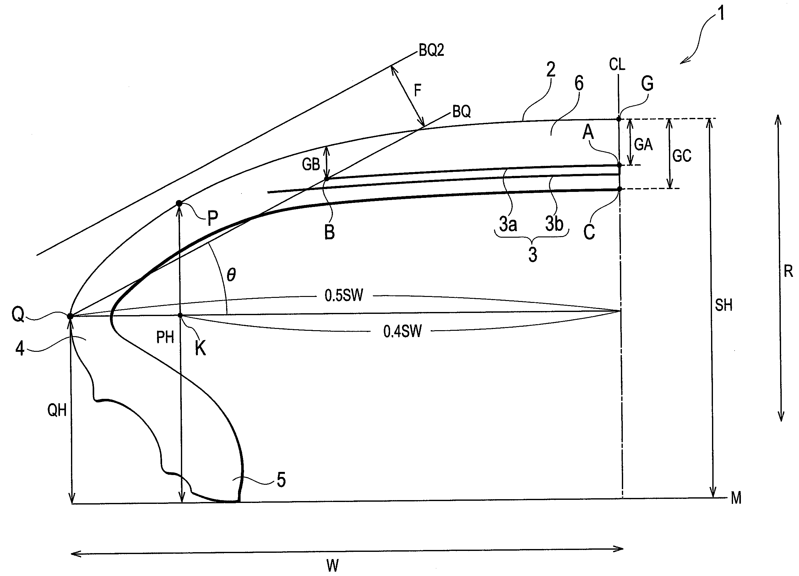
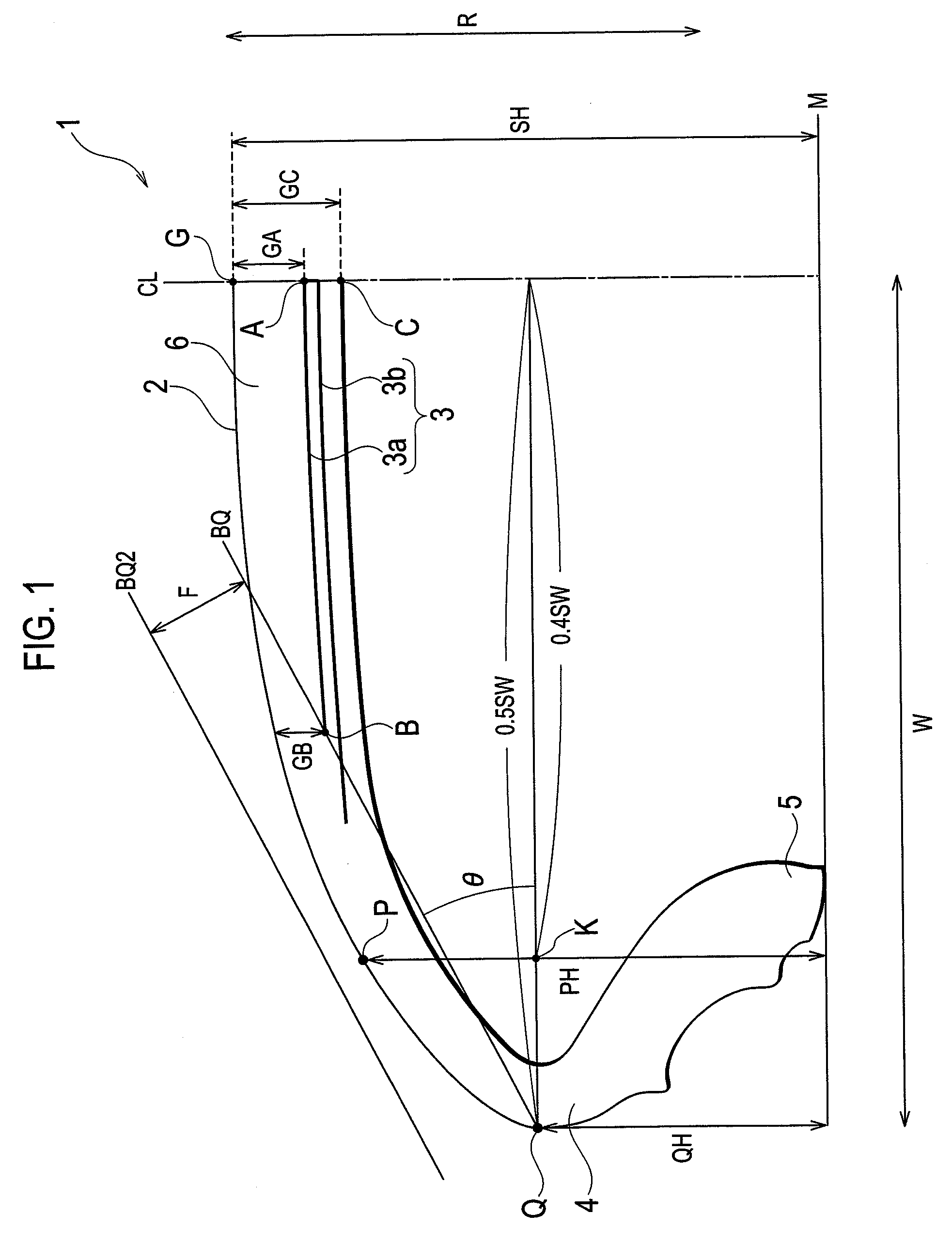
[0028]Descriptions will be given below of a pneumatic tire 1 according to an embodiment.

[0029]FIG. 1 is a cross-sectional view showing a pneumatic tire according to the present embodiment. Please note that the drawing shows only one side of the pneumatic tire 1 from the tire equator line CL.

[0030]As shown in the drawing, the pneumatic tire 1 includes a tread part 2, belt layers 3, sidewall parts 4, and bead toes 5.

[0031]The tread part 2 is a thick rubber layer which contacts a road surface, and is for protecting the belt layers 3 to be described later and the like.

[0032]Each of the belt layers 3 is formed of a plurality of parallel cords covered with rubber, and is disposed on the inner side of the tread part 2 in the radial direction of the tire (an arrow R direction). Here, the belt layers 3 include at least two layers, a shortest belt layer 3a, the length of which in the tire width direction W is shortest, and a longest belt layer 3b, the length of which in the tire width directi...

second embodiment

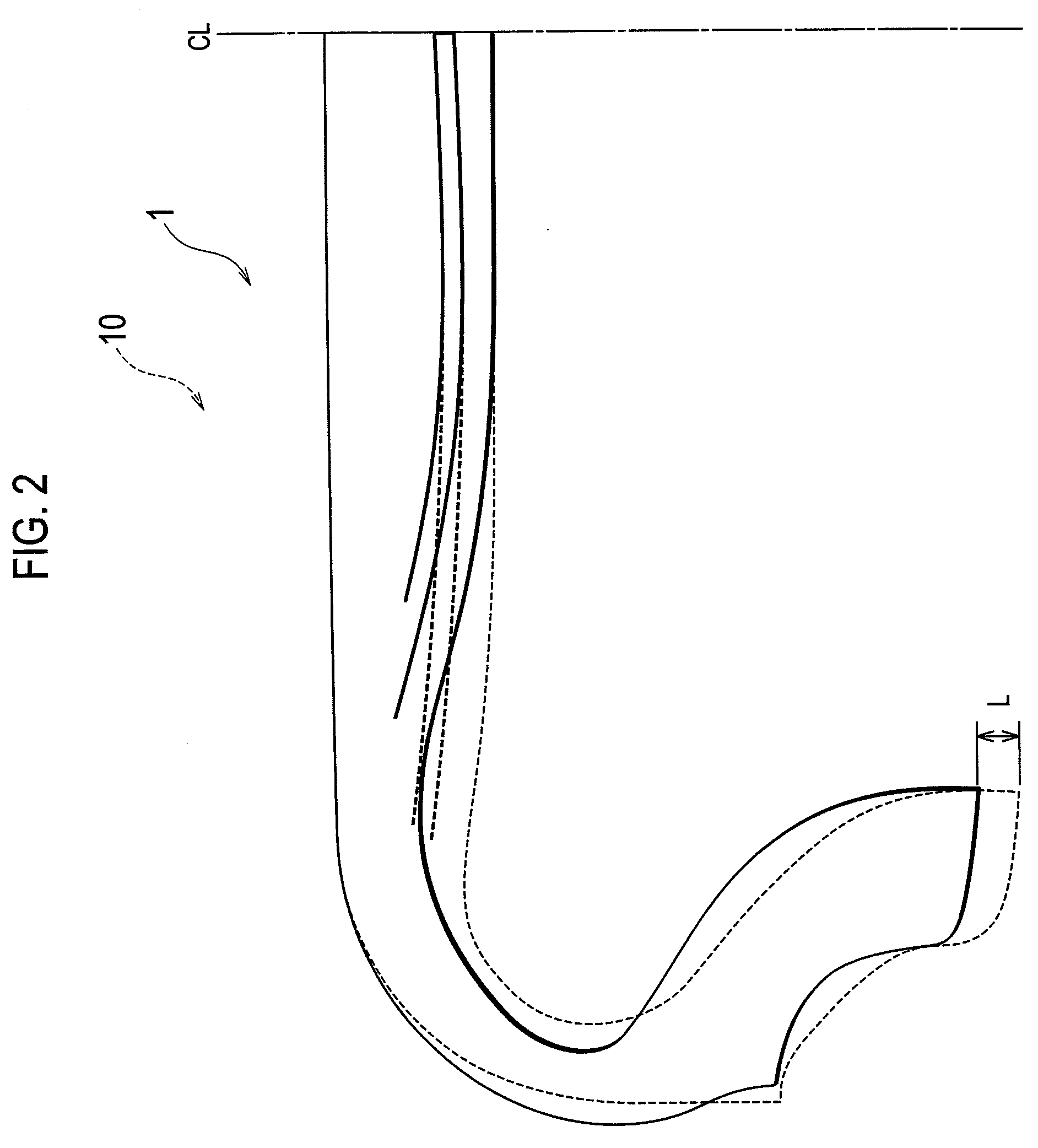
[0059]Descriptions will be given below of a pneumatic tire 1 according to a second embodiment.

[0060]FIG. 5 is a cross-sectional view showing the pneumatic tire 1 according to this embodiment. Please note that the drawing shows only one side of the tire from a tire equator line CL in the pneumatic tire 1.

[0061]As shown in the drawing, the pneumatic tire 1 includes a tread part 2, belt layers 3, sidewall parts 4, and reinforcing layers 7.

[0062]Since the descriptions of the tread part 2, the belt layers 3 and the sidewall parts 4 overlap with those in the first embodiment, descriptions thereof will be omitted.

[0063]In the cross section, each reinforcing layer 7 extends from a position in the inner side in the tire width direction than an edge of a longest belt layer 3b to the vicinity of a line segment SW, and is disposed on the inner side in the radial direction of the tire than the belt layers 3 on the innermost side in the radial direction of the tire. Here, each of the reinforcing ...

third embodiment

[0066]Descriptions will be given below of a pneumatic tire 1 according to a third embodiment.

[0067]The pneumatic tire 1 includes a tread part 2, belt layers 3, and sidewall parts 4.

[0068]Since the descriptions of the tread part 2, the belt layers 3 and the sidewall parts 4 overlap with those in the first embodiment, descriptions thereof will be omitted.

[0069]FIG. 6 is a view showing the belt layers 3 in this embodiment.

[0070]Assume a case where an acute angle formed by each cord 30 which forms a longest belt layer 3b, and which inclines in relation to a tire equator line CL, indicates an angle θ1, and where an acute angle formed by each cord 30 which forms a shortest belt layer 3a, and inclines in relation to the tire equator line CL indicates an angle θ2, in the cross section, as shown in the drawing. In such a case, the angle θ1 is larger than the angle θ2.

[0071]Furthermore, the cords 30 which form the shortest belt layer 3a and the cords 30 which form the longest belt layer 3b in...


PUM


Abstract

The present invention provides a pneumatic tire in which the rolling resistance can be reduced without reducing the wear resistance and the durability.
The present invention is a pneumatic tire including a tread part contacting a road surface, at least two belt layers each formed of a plurality of parallel cords covered with rubber, and a pair of bead toes. Here, an angle at which the line segment BQ and the line segment SW cross is 50° or smaller when, in a cross section including the axis of rotation: the ends of a shortest belt layer, which is the shortest one, in length in a tire width direction, of the belt layers are set to be points B; points on a tire surface, between which the width of the tire is the widest, are set to be points Q; a line segment connecting each point B and the corresponding one of the points Q is set to be a line segment BQ; and a line segment connecting the pair of points Q is set to be a line segment SW.

Description

TECHNICAL FIELD[0001]The present invention relates to a pneumatic tire including: a tread part, which contacts a road surface; at least two belt layers each including a plurality of parallel cords covered with rubber; and a pair of bead toes.BACKGROUND ART[0002]Heretofore, a pneumatic tire which has reduced rolling resistance has been developed (for example, refer to Patent Document 1).[0003]As a method of reducing rolling resistance, devised, in recent years, have been a method by reducing the tan δ of rubber used for a tread part, a method by making a gauge of a tread part shallow to the limit, and the like (for example, Japanese Patent Application Laid-open Publication No. 2002-205513).DISCLOSURE OF THE INVENTION[0004]However, when the method by reducing the tan δ of rubber used for a tread part is employed, a problem arises that the wear resistance may be reduced.[0005]In addition, when the method by making a gauge of a tread part shallow to the limit is employed, a problem aris...

Claims


Application Information

Patent Timeline
Patent Type & Authority Applications(United States)
IPC IPC(8): B60C9/28
CPCB60C3/04B60C9/09Y10T152/10765B60C9/28B60C9/0292B60C9/2009Y02T10/86
Inventor ABE, AKIHIKO
Owner BRIDGESTONE CORP
Why Eureka
Try Eureka