Heat Exchanger

Inactive Publication Date: 2009-04-23
TAT TECHNOLOGIES
View PDF17 Cites 18 Cited by
  • Summary
  • Abstract
  • Description
  • Claims
  • Application Information

AI Technical Summary

Benefits of technology

[0021]The purpose of the present invention is the development of a highly effective, lightweight, compact and reliable hea

Problems solved by technology

This leads to a poorer unitary thermal performance resulting in a larger volume and increased weight.
An additional point of concern is the possible breakage of tubes as a result of vibration-induced fatigue failures.
Owing to these considerations the shell and tube heat exchanger cannot meet the reliability required e.g. for modern jet engines.
It is well known that braze joints have polycrystalline cast structure of lower density and some characteristic micro-defects such as micro-pores, blisters, voids, oxide inclusions which result in bonding imperfections.
Such small discontinuity flaws are usually not detectable on a finished new product which successfully passes a routine standard leak test.
However, after a certain period of operational use, such micro-defects may develop into more serious imperfections under the influence of differential heat stresses and resulting in internal leakages.
In certain applications such a failure mode may prove particularly critical e.g. in a fuel/oil heat exchanger when the oil

Method used


Image

  • Heat Exchanger
  • Heat Exchanger
  • Heat Exchanger

Examples


Example

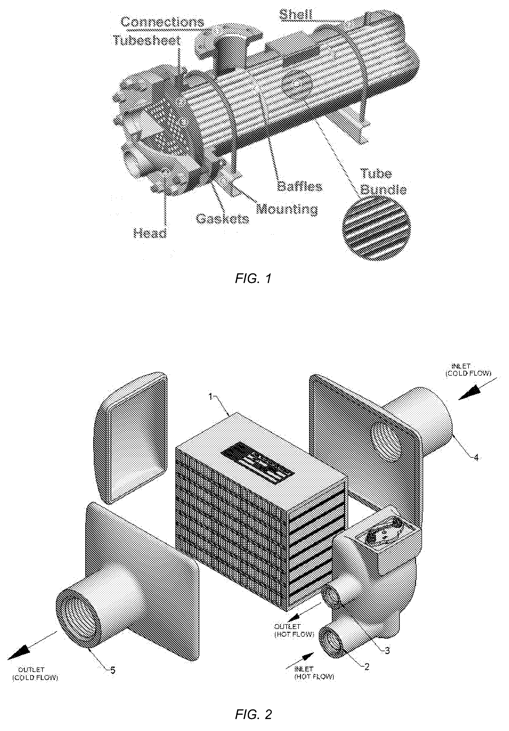
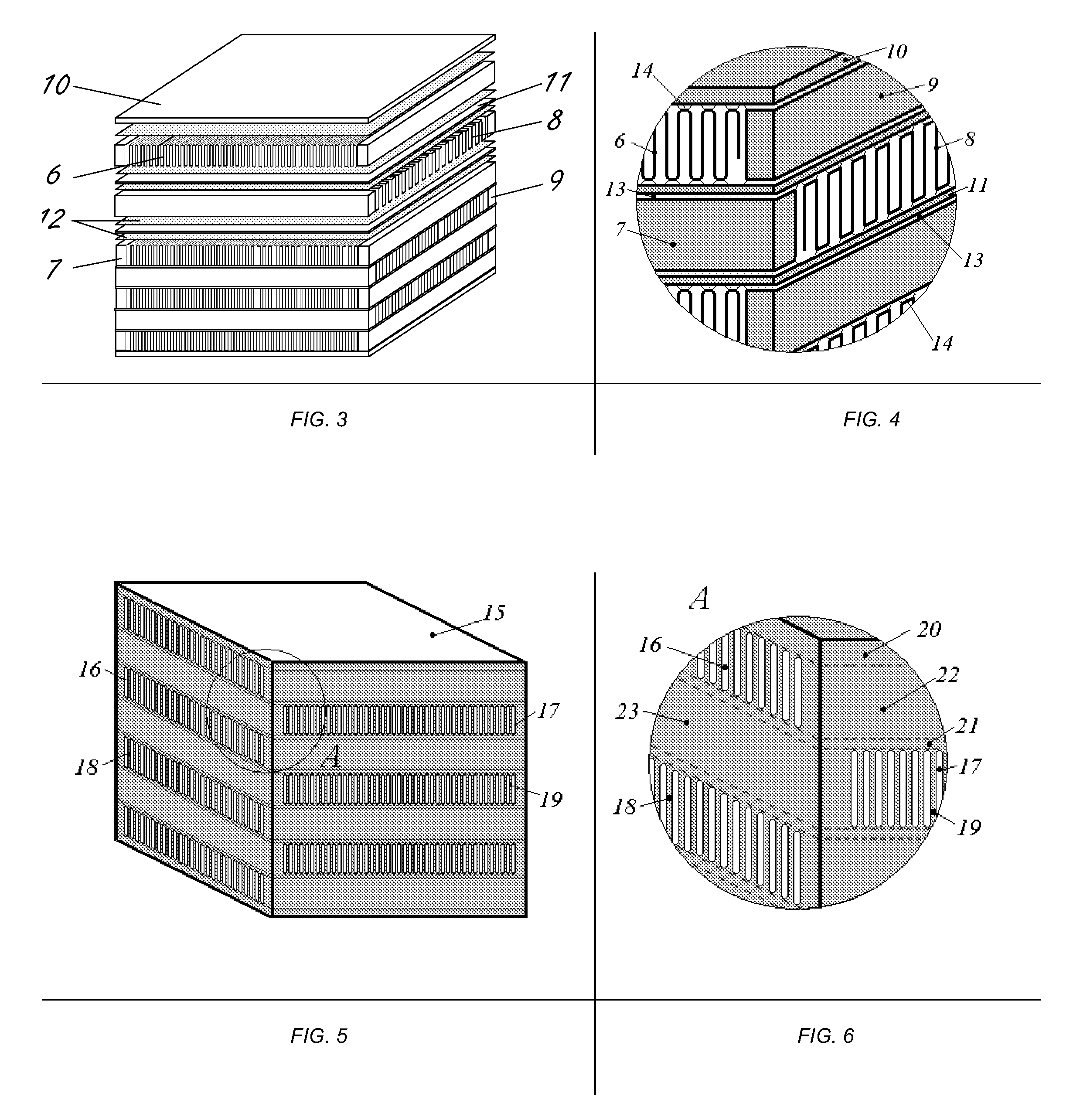
[0039]The objective is achieved by using a core assembly manufactured in part or in full as a one-piece monolithic metallic block, similar in configuration to a conventional fin-and-plate heat exchanger. In such a structure, the brazing seams, which usually are a source for imperfections and internal leakages, have been eliminated. All the voids in the suggested construction allowing the passage of both the hot and cold flows are obtained by removal of material from a single piece of metal.

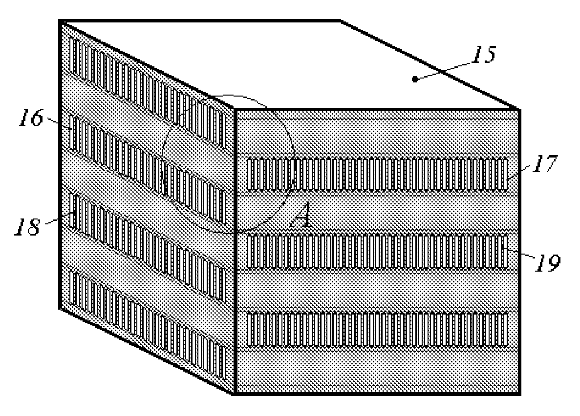
[0040]FIGS. 5, 6 show one embodiment of the invention where a core assembly is manufactured as a one-piece monolithic metallic block 15 having two sets of parallel and mutually perpendicular flow channels 16 and 17. Each of these channels are provided for one of the hot and cold flow passages.

[0041]The aggregate volume of channels 16 (FIGS. 5, 6) and their respective headers 38 and 39 (FIG. 14) form a confined space for the cold flow passage, while the aggregate volume of Channels 17 (FIGS. 5, 6) ...


PUM


Abstract

The invention presents a MONOBLOC fin and plate heat exchanger design preventing internal leakages and intermixing of high-temperature and low-temperature flows, e.g. oil and fuel. This is achieved through a particular configuration of the heat exchanger, whereby its core assembly is completely or partially produced from a one-piece monolithic metallic block. Owing to that, all brazed seams, which in conventional fin and plate heat exchangers contact with both hot medium and cold medium flows, are fully abolished thereby excluding a source for imperfections usually developing in brazed joints and base metal in the process of pressure-temperature cyclic loading. Employing custom-made individual fins allows about two-fold increase in the strength of brazed joints in comparison with ordinary corrugated fins (due to doubling of the brazed surface). As a result, the suggested configuration allows the design of a high reliability compact heat transfer device for much higher operating pressures than what may be achieved in the conventional fin and plate heat exchanger. This invention may be used in different fields of modern technology, especially for aeronautical engine applications, where the challenge of ensuring reliability levels of one failure in millions of (fleet-cumulative) flight hours, and operating pressure levels of thousands of pounds per square inch, must be met.

Description

BACKGROUND OF THE INVENTION[0001]The present invention relates to heat exchange technology and equipment, and more particularly concerns design and methods of manufacture of heat exchangers for aeronautical applications. It may prove to be most advantageous for the production of highly reliable compact heat transfer devices, particularly adapted for high pressure operating conditions.[0002]At present in aeronautical engineering both the shell-tube and fin-plate heat exchangers are widely used for high pressure applications. With rising pressure magnitudes, however, the fin and plate heat exchanger will be limited in the future.DESCRIPTION OF THE PRIOR ART[0003]The classical shell and tube heat exchanger is diagrammatically shown in FIG. 1.[0004]This type of heat exchanger is suited for high pressures in view of its tubular construction which provides uniform stresses. At the same time it suffers from some serious disadvantages.[0005]The shell and tube heat exchanger transfers heat t...

Claims


Application Information

Patent Timeline
IPC IPC(8): F28D7/00
CPCF28F3/02F28F7/02F28F3/025
Inventor OSTERSETZER, SHLOMOGORODETZKY, AVRAHAM
Owner TAT TECHNOLOGIES
Why Eureka
Try Eureka