[0011]In such a conveying roller, the bearing point is preferably formed from an axle which can be fastened in a rotationally fixed manner to a roller frame at least in one direction of rotation, and / or wherein the bearing is formed from a rolling bearing and / or a
plain bearing and / or wherein the braking device is a centrifugal brake, and / or wherein the inhibiting device is a
freewheel. Freewheels have the
advantage that they are quiet in operation and have a low
frictional resistance in the freewheeling direction. By contrast, toothings which can be locked in one direction of rotation by means of a resilient pawl which engages in the toothing and are freewheeling in the other direction have the
advantage that a higher torque can be transmitted. Rolling bearings have a lower
frictional resistance than plain bearings, although plain bearings have a higher strength when subjected to
impact loading. A centrifugal brake has the
advantage that it is self-operated, with the result that the
centrifugal force, and hence the braking force, is dependent on the rotational speed of the braking elements. Other design forms of inhibiting devices are also conceivable, such as, for example, clutches, brakes or the like.
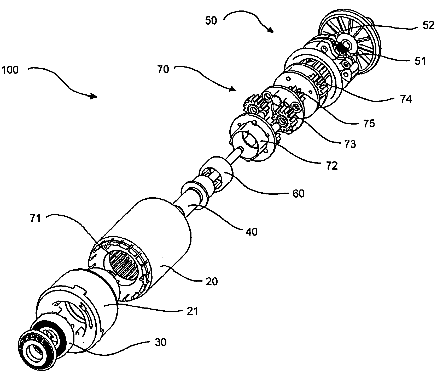
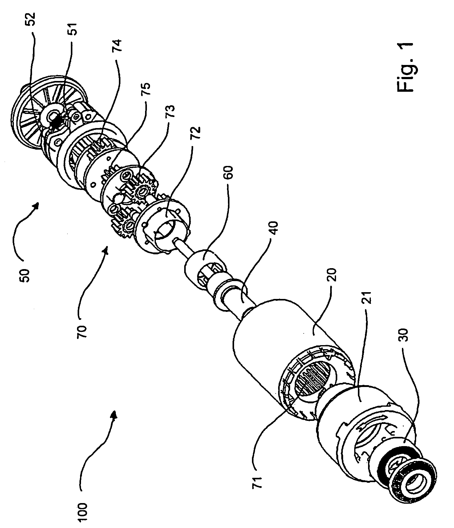
[0013]It is further considered advantageous if the conversion means in such a conveying roller is an epicyclic gearset which can be operated in two-shaft operation and / or in three-shaft operation and / or in multishaft operation, wherein at least a first drive is formed by the casing element or a part connected in a rotationally fixed manner to the casing element, and wherein an output is connected to the braking drive in a substantially rotationally fixed manner at least in one direction of rotation and / or a second drive is formed by the bearing point. It is thus possible, for example, even at a relatively slow rotational speed of the casing element, to achieve a sufficient rotational speed of a driver of a centrifugal brake in order to achieve a sufficient
centrifugal force of braking elements of the centrifugal brake. Preference is given to using a single-stage or multistage planetary gearset in two-shaft operation or in three-shaft operation. Here, the drive in the bearing point is preferably fastened in a rotationally fixed manner in relation to the mounting of the conveyor roller in a roller frame. However, it is also possible to drive the bearing point, for example, externally in a separate manner, with the result that the relative speed between the drives can be varied and the braking action can thus be adjusted.
[0014]Preferably, such a conveying roller is designed in such a way that the inhibiting device is provided on the frame side on the bearing point and / or between the bearing point and conversion means and / or inside the conversion means and / or between the conversion means and braking device and / or between the braking device and casing element. A frame-side mounting of the inhibiting device has the advantage that it can be more easily retrofitted, for example, to existing roller conveyors. In addition, the inhibiting device is more readily accessible during maintenance and repair. A further advantage is that the remaining components of the conveying rollers can stay the same, with the result that such conveying rollers can be used with or without an inhibiting device in different conveying paths, which means that the manufacture for different conveying rollers using the same parts is cheaper. A mounting between the bearing point, in particular an axle, and the conversion means, in particular a planetary gearset, has the advantage that an inhibiting device has only to transmit the torques of the drive
train but does not have to take up the load of the pallets. The other stated types of mounting also have this advantage. Furthermore, a mounting inside the conversion means or between the braking device and conversion means or between the braking device and casing element has the advantage that the mounting location can be chosen according to
diameter, torque to be transmitted and rotational speed, with the result that the mounting can be optimally chosen with respect to application and cost.
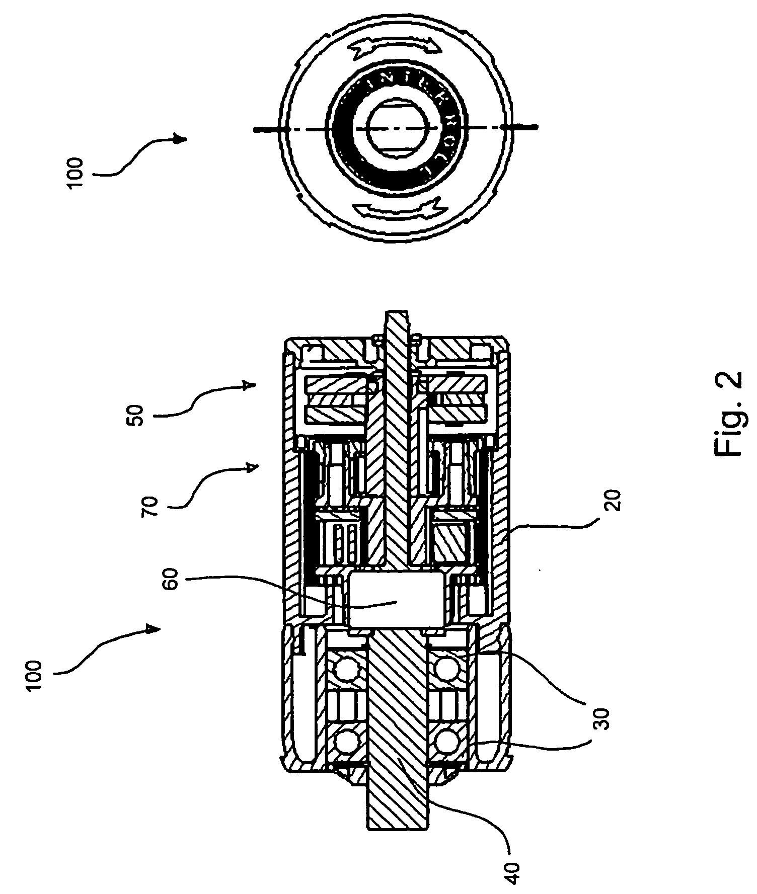
[0018]It is also advantageous in such a conveying roller if the inhibiting device is provided at a point inside the casing element. This has the advantage that the inhibiting device is protected from environmental effects.
[0020]Such a conveying path is preferably inclined with respect to the horizontal in a conveying direction or counter to the conveying direction, wherein the conveying roller is mounted in an orientation transversely to the conveying direction in such a way that a braking action of the braking device is allowed in the direction facing downward along the conveying path and is prevented in a direction facing upward along the conveying path.
[0022]Such a conveying path preferably comprises conveying rollers in which the inhibiting devices are each arranged at different points, in particular at least one conveying roller in which the inhibiting device is arranged on the frame side on the bearing point, and also at least one conveying roller in which the inhibiting device is arranged at a point at which
impact loads which act on the conveying roller during operation do not act on the inhibiting device. This has the advantage that, in regions in which
impact loads occur to an increased degree, for example at the loading and unloading points, the inhibiting devices can be arranged such that they do not have to be designed for the
impact loading, whereas a more cost-effective arrangement can be chosen for other conveying rollers. It is also conceivable for only some of the conveying rollers to be braked and / or equipped with an inhibiting device.

