Touch panel

a technology of carbon nanotubes and touch panels, applied in the direction of contacts, contact surface shapes/structures, instruments, etc., can solve the problems of uneven resistance over an entire area of the touch panel, poor mechanical durability of the ito layer, and relatively complicated methods

Active Publication Date: 2009-04-23
TSINGHUA UNIV +1
View PDF98 Cites 114 Cited by
  • Summary
  • Abstract
  • Description
  • Claims
  • Application Information

AI Technical Summary

Problems solved by technology

However, the optically transparent conductive layer (e.g., ITO layer) is generally formed by means of ion-beam sputtering, and this method is relatively complicated.
Furthermore, the ITO layer has generally poor mechanical durability, low chemical endurance and uneven resistance over an entire area of the touch panel.
Additionally, the ITO layer has relatively low transparency.
All the above-mentioned problems of the ITO layer tend to yield a touch panel with low sensitivity, accuracy, and brightness.

Method used


Image

  • Touch panel
  • Touch panel
  • Touch panel

Examples


Embodiment Construction

[0021]Reference will now be made to the drawings to describe, in detail, embodiments of the present touch panel.

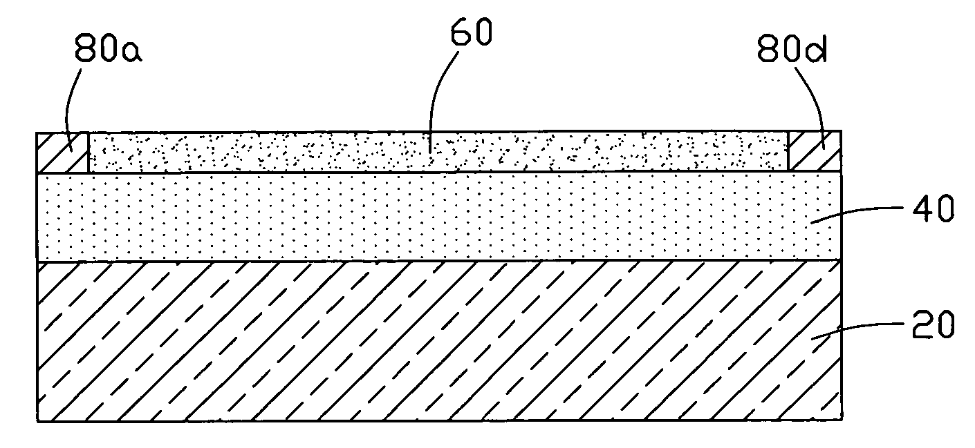
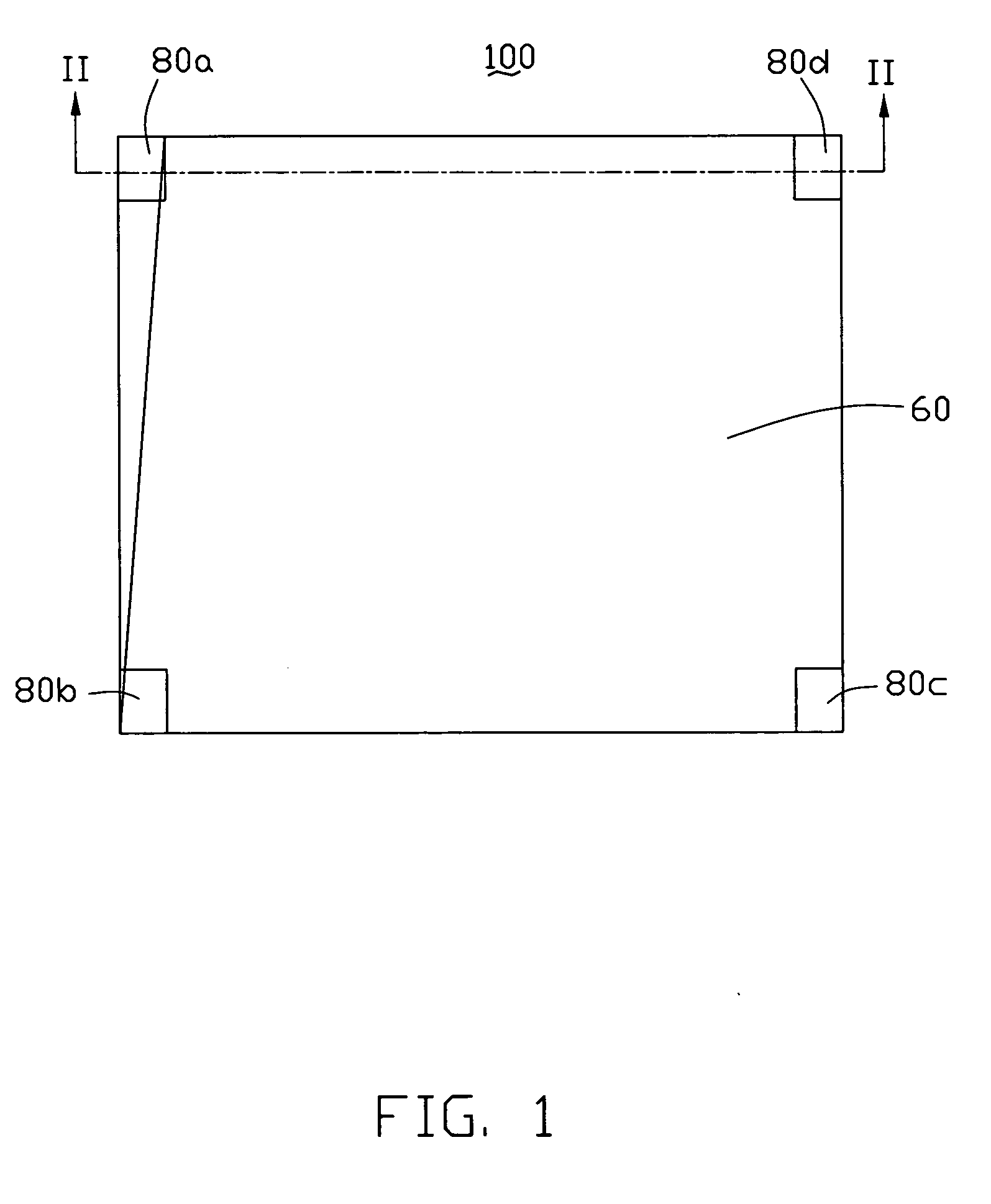
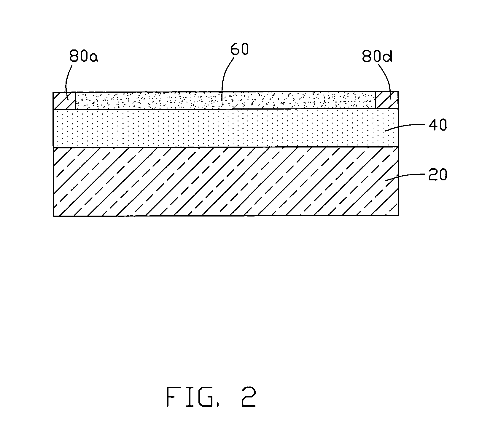
[0022]Referring to FIG. 1 and FIG. 2, a touch panel 100 includes a substrate 20, a transparent conductive layer 40, a hardening layer 60, and at least two metal electrodes.

[0023]The substrate 20 has a first substrate surface and a second substrate surface opposite to the first substrate surface. The substrate 20 is transparent and the surfaces thereof are curved or planar. In the present embodiment, the material of the substrate 20 is glass. The transparent conductive layer is a carbon nanotube structure 40, and is formed on the first substrate surface. The at least two electrodes are formed of foil or conductive metal plating film with low-resistance, e.g., silver plating film or copper plating film. In the present embodiment, the touch panel 100 has four metal electrodes 80a, 80b, 80c, 80d. The metal electrodes 80a, 80b, 80c, 80d are located, separately, on the corners o...


PUM

PropertyMeasurementUnit
thicknessaaaaaaaaaa
temperatureaaaaaaaaaa

Abstract

A touch panel includes a substrate, a transparent conductive layer and at least two separate electrodes. The substrate has a first substrate surface and a second substrate surface opposite to the first substrate surface. The transparent conductive layer includes a carbon nanotube structure formed on the first substrate surface. The at least two separate electrodes are located on a surface of the transparent conductive layer and electrically connected thereto.

Description

RELATED APPLICATIONS[0001]This application is related to commonly-assigned applications entitled, “TOUCH PANEL AND DISPLAY DEVICE USING THE SAME”, filed **** (Atty. Docket No. US17818); “TOUCH PANEL”, filed **** (Atty. Docket No. US17448); “TOUCH PANEL AND DISPLAY DEVICE USING THE SAME”, filed **** (Atty. Docket No. US17889); “TOUCH PANEL AND DISPLAY DEVICE USING THE SAME”, filed **** (Atty. Docket No. US17861); “TOUCH PANEL AND DISPLAY DEVICE USING THE SAME”, filed **** (Atty. Docket No. US17820); “TOUCH PANEL AND DISPLAY DEVICE USING THE SAME”, filed **** (Atty. Docket No. US17862); “TOUCH PANEL AND DISPLAY DEVICE USING THE SAME”, filed **** (Atty. Docket No. US17863); “TOUCH PANEL AND DISPLAY DEVICE USING THE SAME”, filed **** (Atty. Docket No. US18263); “TOUCHABLE CONTROL DEVICE”, filed **** (Atty. Docket No. US18262); “TOUCH PANEL AND DISPLAY DEVICE USING THE SAME”, filed **** (Atty. Docket No. US17888); “TOUCH PANEL AND DISPLAY DEVICE USING THE SAME”, filed **** (Atty. Docket ...

Claims


Application Information

Patent Timeline
Patent Type & Authority Applications(United States)
IPC IPC(8): H01H1/10
CPCG06F3/044G06F3/0443
Inventor JIANG, KAI-LIFAN, SHOU-SHAN
Owner TSINGHUA UNIV
Why Eureka
Try Eureka