
Bicycle control system

a control system and bicycle technology, applied in the direction of anti-theft devices, cycle equipment, pulse techniques, etc., can solve the problems of data not being recognizable or falsely recognized, data cannot be transmitted and received in real time,

Active Publication Date: 2009-04-23
SHIMANO INC
View PDF12 Cites 44 Cited by
  • Summary
  • Abstract
  • Description
  • Claims
  • Application Information

AI Technical Summary

Benefits of technology

The present invention provides a bicycle control system that can recognize a switch operation signal correctly even if there is a communication outage. This is achieved by a switch device with a sensor to detect switch operation, a processing unit to generate an identification code and an operating signal code, and a transmitter to transmit the output signal to a cycle computer. The cycle computer receives the output signal and combines it with the identification code to generate the output signal. This ensures that the switch operation can be correctly recognized by the cycle computer, even if there is a communication outage.

Problems solved by technology

Thus, the data can not be transmitted and received in real time.
Therefore, if a communication outage happens due some interference or interruption in communications, then the data may be unrecognizable or falsely recognized.

Method used


Image

  • Bicycle control system
  • Bicycle control system
  • Bicycle control system

Examples


Embodiment Construction

[0023]Selected embodiments of the present invention will now be explained with reference to the drawings. It will be apparent to those skilled in the art from this disclosure that the following descriptions of the embodiments of the present invention are provided for illustration only and not for the purpose of limiting the invention as defined by the appended claims and their equivalents.

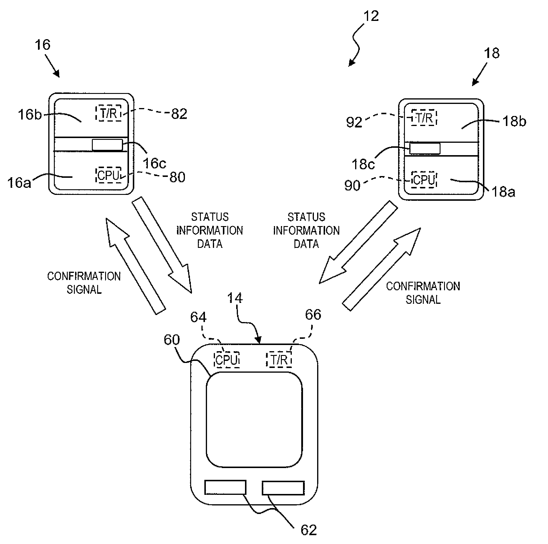
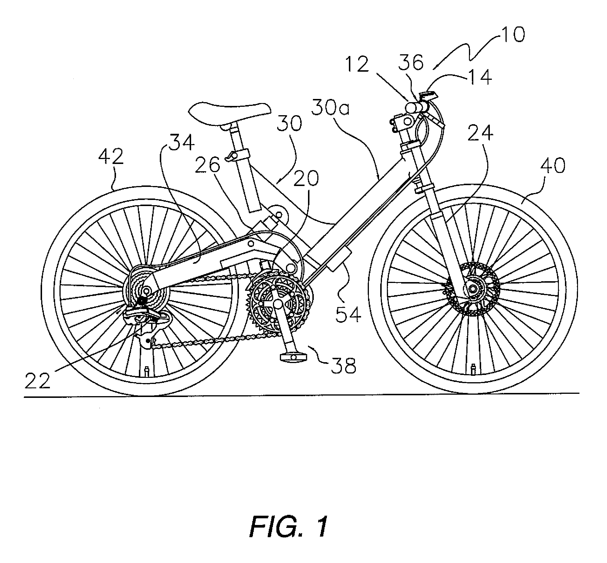
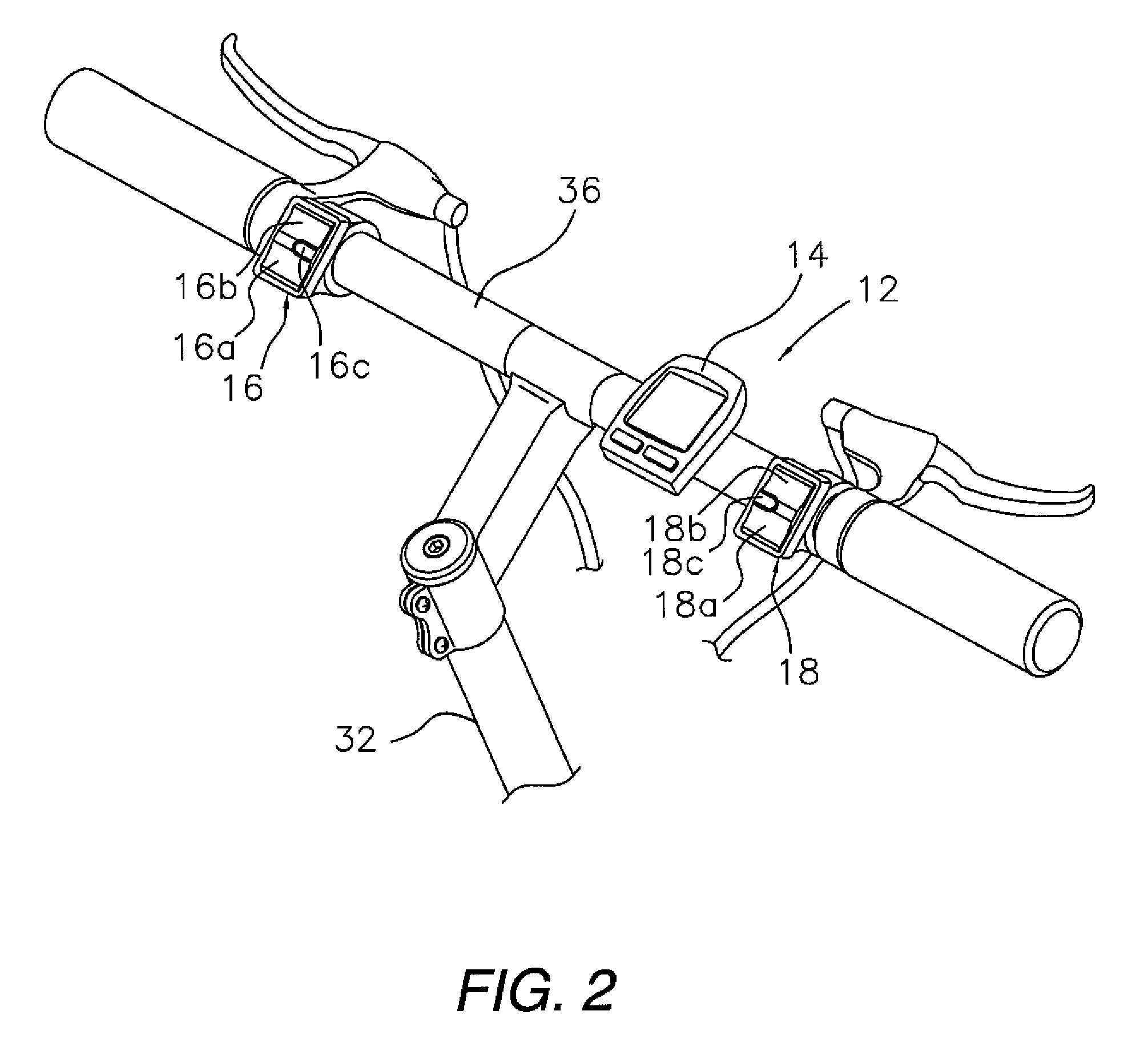
[0024]Referring initially to FIGS. 1 and 2, a bicycle 10 is illustrated that is equipped with a bicycle control system 12 that controls the shifting of the bicycle 10 and the stiffness of the suspension of the of the bicycle 10. Basically, the bicycle control system 12 includes a cycle computer 14, a first electrical switch unit 16 a second electrical switch unit 18, a front electrically powered derailleur 20, a rear electrically powered derailleur 22, a front suspension fork 24 and a rear shock absorber 26. In the illustrated embodiment, the bicycle control system 12 preferably conducts interval w...


PUM


Abstract

A bicycle control system is provided with a switch device and a cycle computer. The switch device includes a switch operation member, a sensor arranged relative to the switch operation member to detect operation of the switch operation member, a processing unit operatively coupled to the sensor and a transmitter arranged to transmit an output signal. The processing unit of the switch device includes an identification code generating member, an operating signal generating member and an output member. The identification code generating member generates identification code related to identification of the switch device. The operating signal generating member generates an operation code indicative of operation of the switch operation member. The output member combines the identification code and the operation code as the output signal to be transmitted by the transmitter of the switch device.

Description

BACKGROUND OF THE INVENTION[0001]1. Field of the Invention[0002]This invention generally relates to a bicycle control system that conducts interval communications from a rider operable switch device to a cycle computer. More specifically, the invention relates to a bicycle control system in which a switch operation signal is correctly recognized by a cycle computer even if a communication outage (e.g., interference or interruption in communications) occurs.[0003]2. Background Information[0004]Bicycling is becoming an increasingly more popular form of recreation as well as a means of transportation. Moreover, bicycling has become a very popular competitive sport for both amateurs and professionals. Whether the bicycle is used for recreation, transportation or competition, the bicycle industry is constantly improving the various components of the bicycle.[0005]Recently, bicycles have been equipped with electrical components to make riding easier and more enjoyable for the rider. Some ...

Claims


Application Information

Patent Timeline
Patent Type & Authority Applications(United States)
IPC IPC(8): B62J6/00
CPCB62M25/08
Inventor TAKEBAYASHI, HARUYUKI
Owner SHIMANO INC
Learn More