
Self-feeding apparatus

a self-feeding and apparatus technology, applied in the field of self-feeding apparatuses, can solve the problems of increased mechanical and electrical complexity, increased safety risks of feeding devices for users, and mechanical complexity of automatic feeders

Inactive Publication Date: 2009-04-23
SCUOLA SUPERIORE DI STUDI UNIVERSITARI E DI PERFEZIONAMENTO SANTANNA
View PDF15 Cites 28 Cited by
  • Summary
  • Abstract
  • Description
  • Claims
  • Application Information

AI Technical Summary

Benefits of technology

[0009]The main purpose of the present invention is to provide an apparatus for the self-feeding of disabled users and elderly people, that would be capable of operating both at a base level to perform the function of assistant for the feeding of people with severe spine lesions and at an higher level to involve the user in the feeding process focusing on her / his residual abilities and offering opportunities for the rehabilitation and diagnosis.
[0012]Still another object of the present invention is to provide an apparatus of the above mentioned type that would be of the easily transportable type and usable in different situation, also thanks to an autonomous battery power source.

Problems solved by technology

Automatic feeders are mechanically more complex, with simple to complex embedded electronics and control systems, and automate a part of, or all of, the process of selecting, getting a portion of food and offering it to the user.
The disadvantage is in their increased mechanical and electrical complexity, which results in a feeding device with greater safety risks to the user.
Despite their effectiveness the commercially available self-feeders for disabled people are still not being utilized in large numbers.
As a matter of fact, these are still too expensive, too difficult to use, unreliable, inconvenient, difficult to transport, unattractive and too time-consuming in set up.
It has been noticed that, even in those case wherein the operating effectiveness is higher, they are unable to meet the needs of users with minimum head and trunk control, i.e. with the most severe disability degree.

Method used


Image

  • Self-feeding apparatus
  • Self-feeding apparatus
  • Self-feeding apparatus

Examples


Embodiment Construction

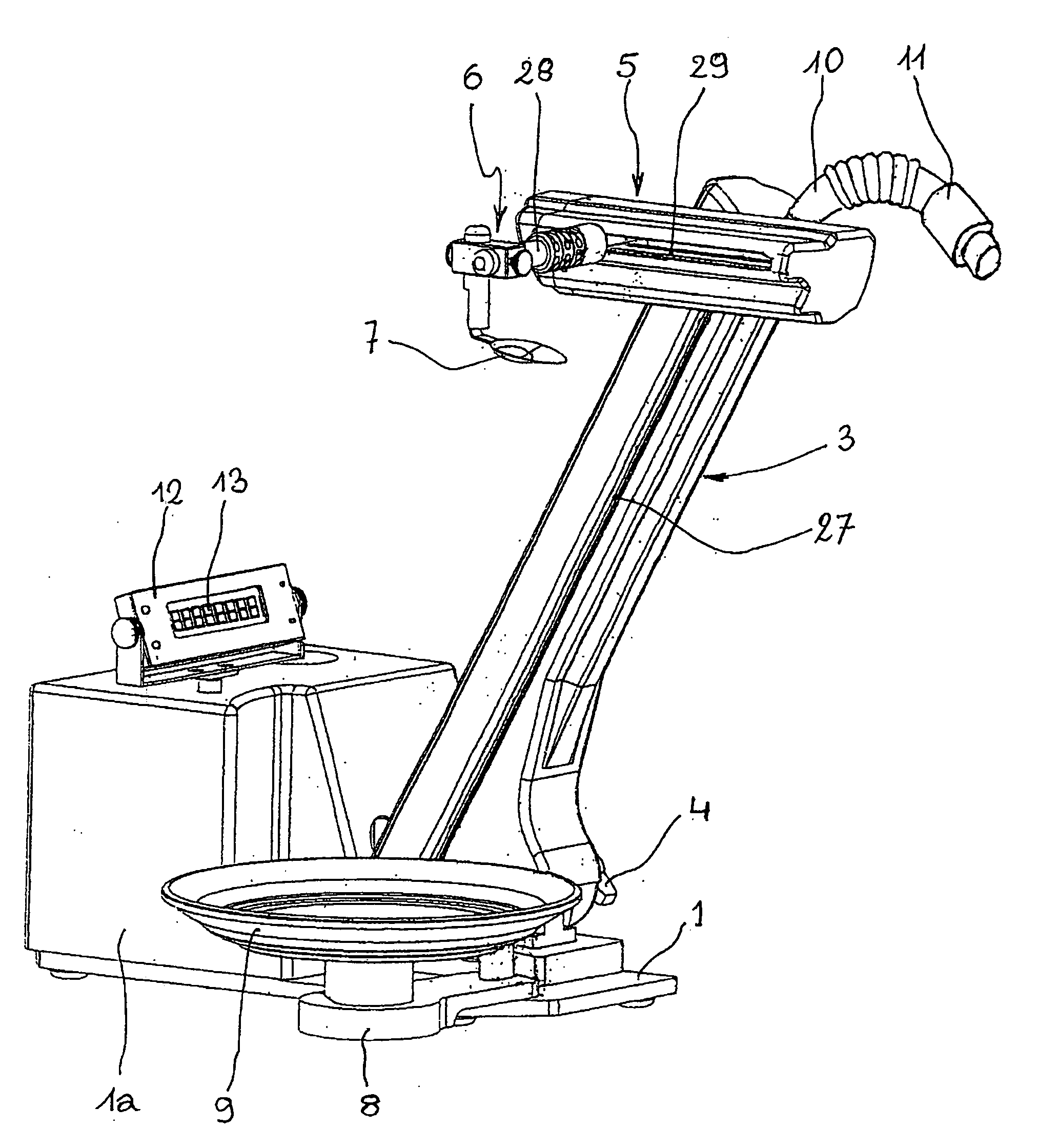
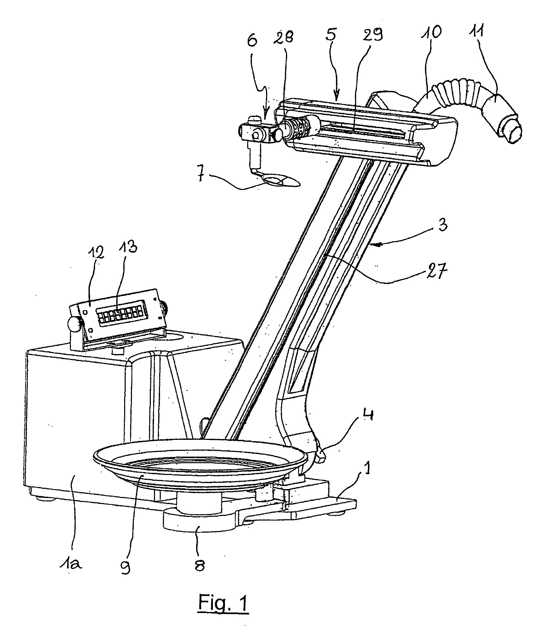
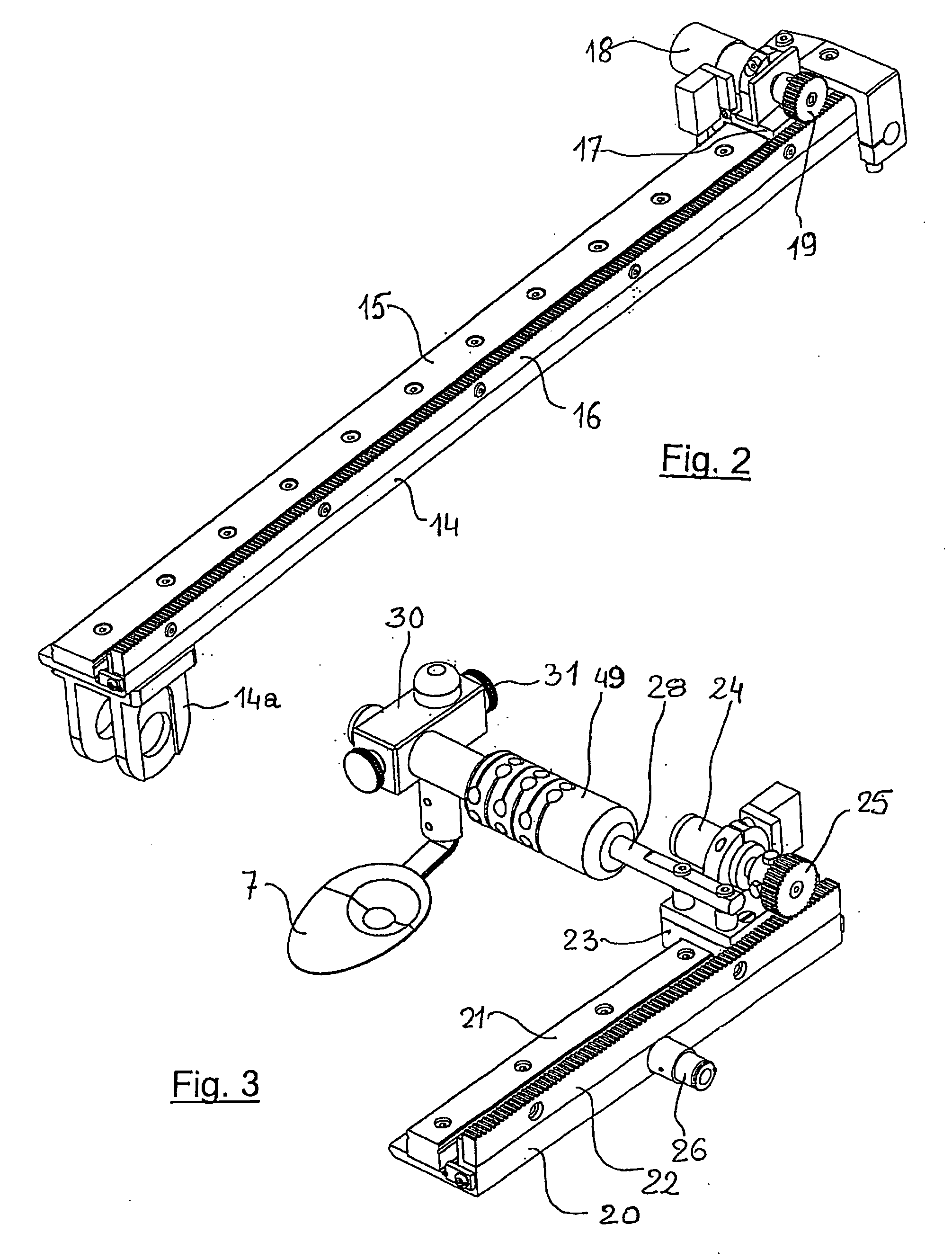
[0031]With reference to FIG. 1, the self-feeding apparatus according to the invention comprises a support base 1 for a box-type frame 1a containing tanks for liquid food and beverages (which will be described later on) as well as the apparatus electronics, and a first arm 3, slanted and connected to the base 1 through a rotoidal joint 4 allowing the inclination of arm 3 to be adjusted between two limit positions, i.e. a substantially vertical position and a substantially horizontal position. A second substantially horizontal arm 5, is mounted on the arm 3 in a longitudinally slidable fashion. On second arm 5 a support, generally indicated at 6, is mounted for a food scooping means, such as cutlery, in particular a spoon 7, said support 6 being also slidable longitudinally on second arm 5. Furthermore a third arm 8 extends horizontally from support base 1 and is equipped with a support 9 for a plate, not shown, or more in general a container for solid food to be fed to the disabled u...


PUM


Abstract

A self-feeding apparatus for the disabled and elderly, which comprises: a support base a holder for an open food container, pivotally connected to the base; an article for scooping food from the container; a system for moving the scooping article from a food scooping position from the container and a food dispensing position at a selected height from the base corresponding to the user's mouth. The system includes a first arm slantingly extending from the base and a second arm, arranged in a substantially horizontal position and slidably mounted on the first arm, the food scooping article being slidably mounted on the second arm. A motor is further provided for sliding the second arm along the first arm and the food scooping article along the second arm and for rotating the food container holder. At least one tank for liquid or semi liquid food and for beverages is placed on the base and a conveyor is provided for transporting the food from the tank to the user's mouth. The apparatus also has a programming and control system that includes a mouth operable control at the outlet end of the conveyor.

Description

FIELD OF THE INVENTION[0001]The present invention relates to an apparatus for the self-feeding of disabled or elderly people.DESCRIPTION OF THE PRIOR ART[0002]Many devices and apparatuses are known aiming at restoring a certain degree of independence in the process of eating to people with various levels of disability. They range from low-tech solutions such as the device commercially known as “Eatery” to robotic hi-tech solutions such as the apparatuses sold under the names “Handy 1” and “My Spoon”. Their specific design goals differ from one case to another one. In some cases the aim is to provide a low-cost and easily manufactured device or a portable, small and easy-to-use device. In other cases attention has been paid to the modularity and adaptability to the user needs. Other differences among the various devices proposed till now concern their user interface, their control structure, their mechanical form and artifacts, and their levels of user involvement in the device opera...

Claims


Application Information

Patent Timeline
Patent Type & Authority Applications(United States)
IPC IPC(8): A61F4/00
CPCA47G21/08
Inventor GUGLIELMELLI, EUGENIODI LAURO, GIUSEPPINA ANNACHIARUGI, FEDERICOGIACHETTI, GIACOMOPERRELLA, YVESPISETTA, ANDREASCOGLIO, ANDREA
Owner SCUOLA SUPERIORE DI STUDI UNIVERSITARI E DI PERFEZIONAMENTO SANTANNA
Learn More