Extension cord featuring length adjustable ends

a technology of extension cords and ends, applied in the direction of flexible lead accommodation, coupling device connections, two-part coupling devices, etc., can solve the problems of unsightly jumbled extension cords, less attractive work areas, and inconvenient routing of extension cords through small spaces, so as to avoid kinking, the effect of length adjustabl

Inactive Publication Date: 2009-04-23
SUMIDA WESLEY K
View PDF21 Cites 19 Cited by
  • Summary
  • Abstract
  • Description
  • Claims
  • Application Information

AI Technical Summary

Benefits of technology

[0019]Another object of the present invention is to provide an extension cord which is length adjustable but avoids kinking.
[0020]Another object of the present invention is to provide an extension cord which is length adjustable and can still be readily routed through small

Problems solved by technology

A common problem associated with this large number of extension cords extending from electric equipment, such as computers, is extension cord management.
Having a large number of extension cords extending from a computer can create a variety of problems.
The extension cords can be in an unsightly jumble making a work area less attractive.
Furthermore, extension cords have a propensity to be either a little bit too short or too long and hence difficult to keep neat and out of the way of a user.
This can cause other extension cords to then be too short or otherwise result in a less than optimally oriented work environment.
However, coiled extension cord also have drawbacks.
By coiling the extension cord it becomes effectively thicker making it more difficult to route such an extension cord between a back edge of a desk and a wall or cubicle divider, or otherwise routing the extension cord

Method used


Image

  • Extension cord featuring length adjustable ends
  • Extension cord featuring length adjustable ends
  • Extension cord featuring length adjustable ends

Examples


second embodiment

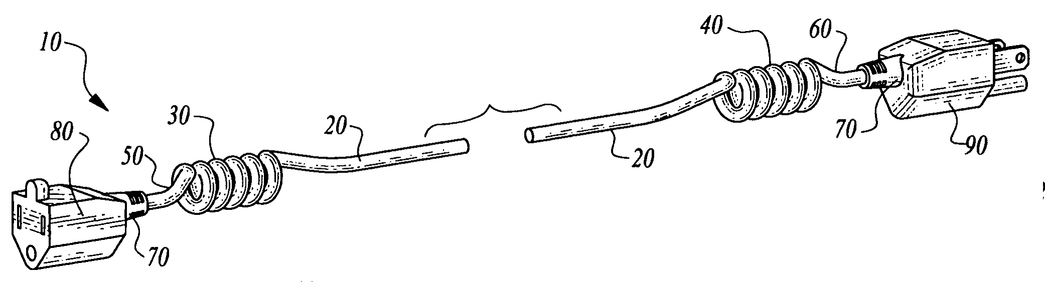
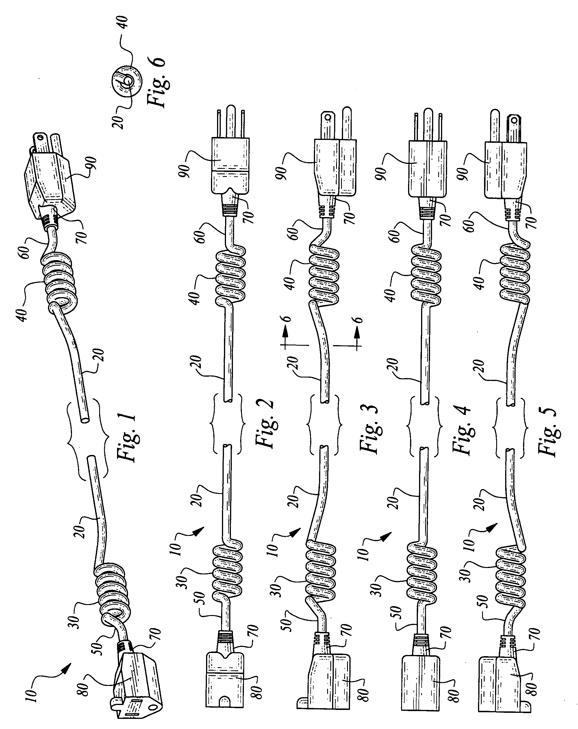
[0041]As one non-limiting example, an overall extension cord can be provided which is six feet long before any elongation. With three inches provided for each stub 50, 60 and each connector 80, 90 and three inches provided for each coil 30, 40, five feet of cable remain for the central portion 20 of the extension cord 10. In a second embodiment, the stubs 50, 60 and connectors 80, 90 can take up six inches each of length and the coils 30, 40 can each take up six inches length, such that four feet of the cable remain within the central portion 20 of the extension cord 10.

[0042]If desired, the central portion 20 could be shorter. Most preferably, central portion 20 would only be shorter in shorter extension cords, such as perhaps a three foot extension cord where the central portion 20 could be two feet long and with three inches for each of the coils 30, 40 and three inches for the stub 50, 60 and connector 80, 90 combinations at each end of the extension cord 10. It is also conceiva...

embodiment 610

[0055]FIGS. 12A and 12B show a power strip extension cord 610 of similar form to the extension cord 10 of the preferred embodiment. A male connector 90 is shown at one end of the power strip extension cord 610 similar to the male connector 90 on the extension cord 10 of the preferred embodiment. However, the female connector 80 is replaced in this power strip extension cord embodiment 610 with a power strip 680. The power strip 680 includes a switch 682 which can selectively connect and disconnect the power strip 680 to the male connector 90 on the power strip extension cord 610. A light 684 is coupled to the power strip 680 in a manner which causes the light 684 to be illuminated when the power strip 680 is active with the switch closed, and the light 684 is darkened when the power strip 680 is deactivated by opening of the switch 682. The power strip 680 includes a housing 686 which includes a plurality of receptacles 688 therein, each of the receptacles 688 having multiple openin...


PUM


Abstract

An extension cord is provided with a central portion which is uncoiled, this central portion bounded on either end by a first coil and a second coil. Each of these coils are length adjustable while the central portion is substantially non-extendible. The extension cord can be fixed in position at a point along the central portion or routed through a narrow space at the central portion and still facilitate length adjustability at two different locations adjacent ends of the cord. Connectors are provided at ends of the cord. The connectors can be male and female power plug connectors for delivery of electric power or can be data cables or combined data and power cables. For instance, USB extension cords, SCSI extension cords, S-VIDEO extension cords, ethernet extension cords, RCA extension cords and power strip extension cords can provide various different connectors for the length adjustable extension cord of this invention.

Description

FIELD OF THE INVENTION[0001]The following invention relates to electric extension cords. More particularly, this invention relates to electric extension cords which have a variety of different connectors at ends thereof for either transmitting power, electric signals, or both and which feature at least portions of the cord being coiled for length adjustability.BACKGROUND OF THE INVENTION[0002]Most electric equipment is characterized in that it has at least one and often multiple separate electrically conductive cords extending therefrom. These cords can generally be referred to as extension cords and include an electrically conductive path (sometimes a plurality of such paths) surrounded within an insulating jacket. The cords have appropriate connectors at ends thereof for connecting to the electric equipment on one end and to peripheral devices or power supplies at the other end.[0003]For instance, with computer equipment a computer will typically have a power extension cord which ...

Claims


Application Information

Patent Timeline
IPC IPC(8): H01R13/72
CPCH01R13/72H01R24/22H01R31/06H01R25/003H01R24/30
Inventor SUMIDA, WESLEY K.
Owner SUMIDA WESLEY K
Why Eureka
Try Eureka