Fuel Cell Vehicle

a fuel cell and vehicle technology, applied in the direction of driver input parameters, computation using non-denominational number representation, process and machine control, etc., can solve the problems of poor fuel economy and poor drivability, and achieve the effect of improving drivability and fuel consumption, reducing the friction coefficient of detected road surfaces, and increasing the tendency of slipping

Inactive Publication Date: 2009-04-23
TOYOTA JIDOSHA KK
View PDF25 Cites 51 Cited by
  • Summary
  • Abstract
  • Description
  • Claims
  • Application Information

AI Technical Summary

Benefits of technology

[0022]The fuel cell vehicle according to another aspect of the invention sets the target value of electrical energy to be output from the fuel cells to the motor and the target value of electrical energy to be output from the accumulator to the motor according to the set power demand, such that in response to the increase of the power demand, the target value of electrical energy to be output from the accumulator to the motor is set based on the road surface friction coefficient. The fuel cell vehicle then controls the fuel cells and the motor to enable the level of electrical energy actually output from the fuel cells to the motor and the level of electrical energy actually output from the battery to the motor to be consistent with the respective target values of electrical energy. The fuel cell vehicle of this aspect adequately sets, in response to the increase of the power demand, the target value of electrical energy to be output from the accumulator to the motor according to the road surface friction coefficient. This arrangement desirably improves the drivability and the fuel consumption, compared with the conventional structure of the fuel cell vehicle.
[0023]In one preferable application of the fuel cell vehicle according to the above aspect of the invention, the target value setting module sets, in response to the increase of the power demand, the target value of electrical energy to be output from the accumulator to the motor based on the road surf

Problems solved by technology

There may thus be problems of poor drivability or po

Method used


Image

  • Fuel Cell Vehicle
  • Fuel Cell Vehicle
  • Fuel Cell Vehicle

Examples


Embodiment Construction

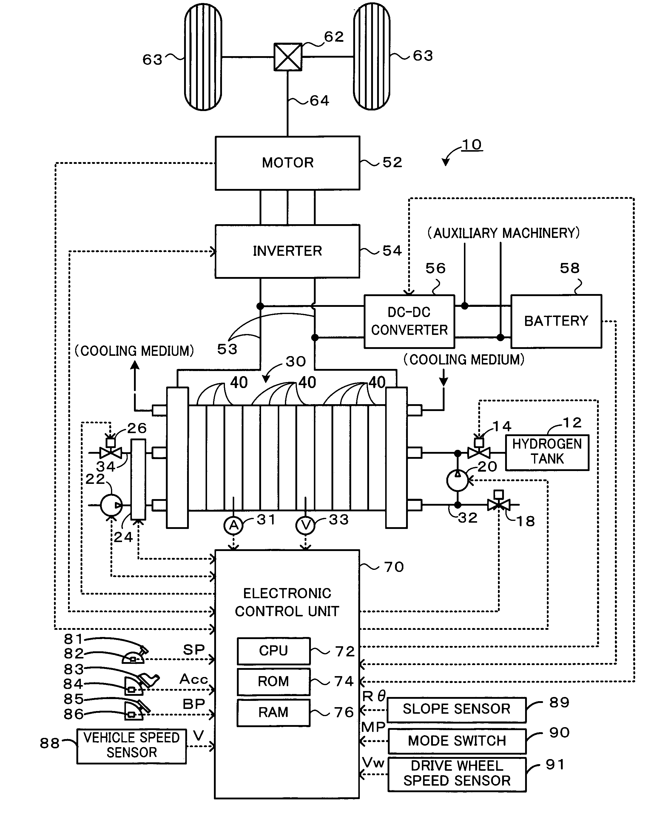
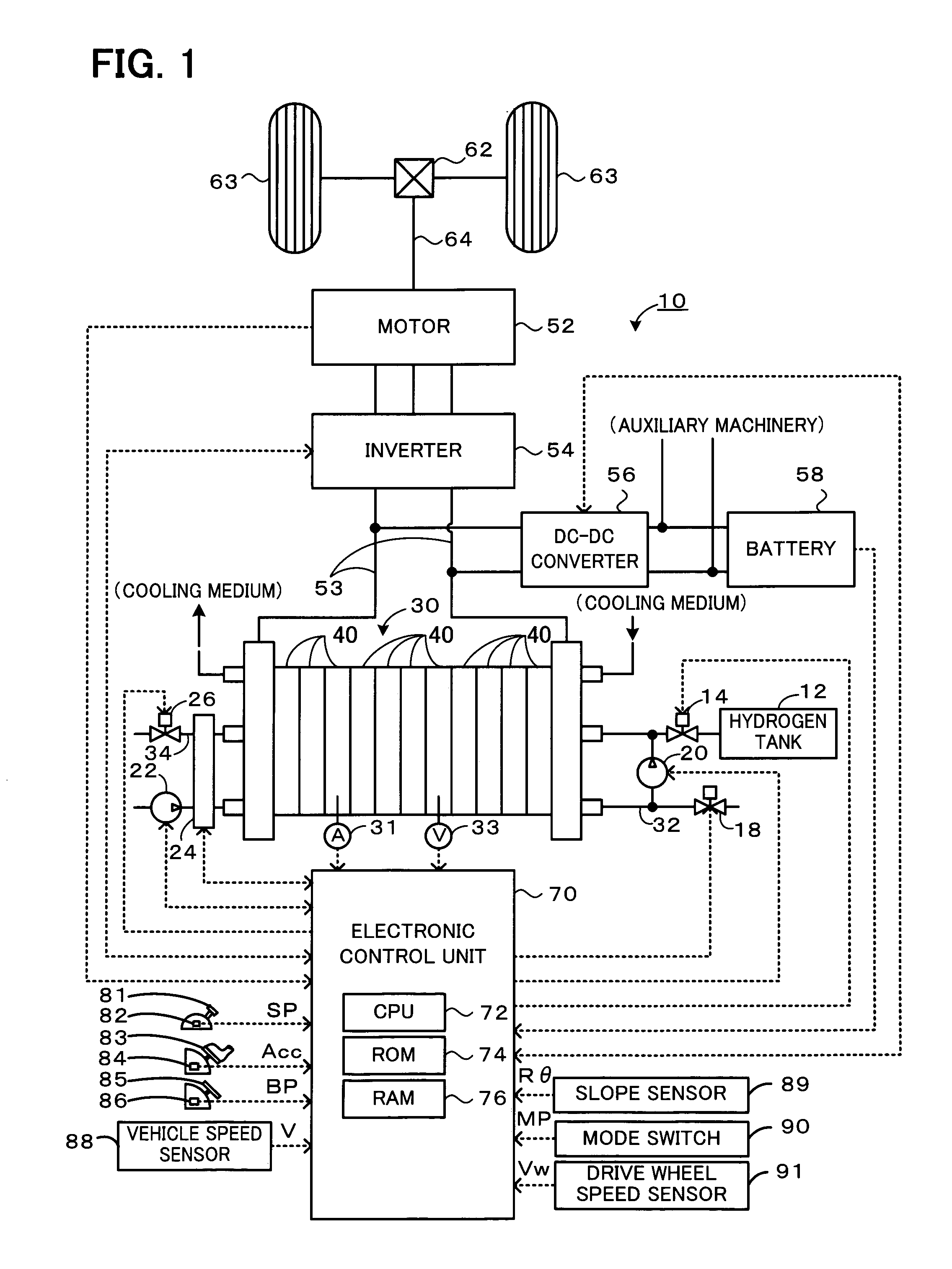
[0045]One mode of carrying out the invention is described below with reference to the accompanied drawings. FIG. 1 schematically illustrates the configuration of a fuel cell vehicle 10 according to one embodiment of the invention.

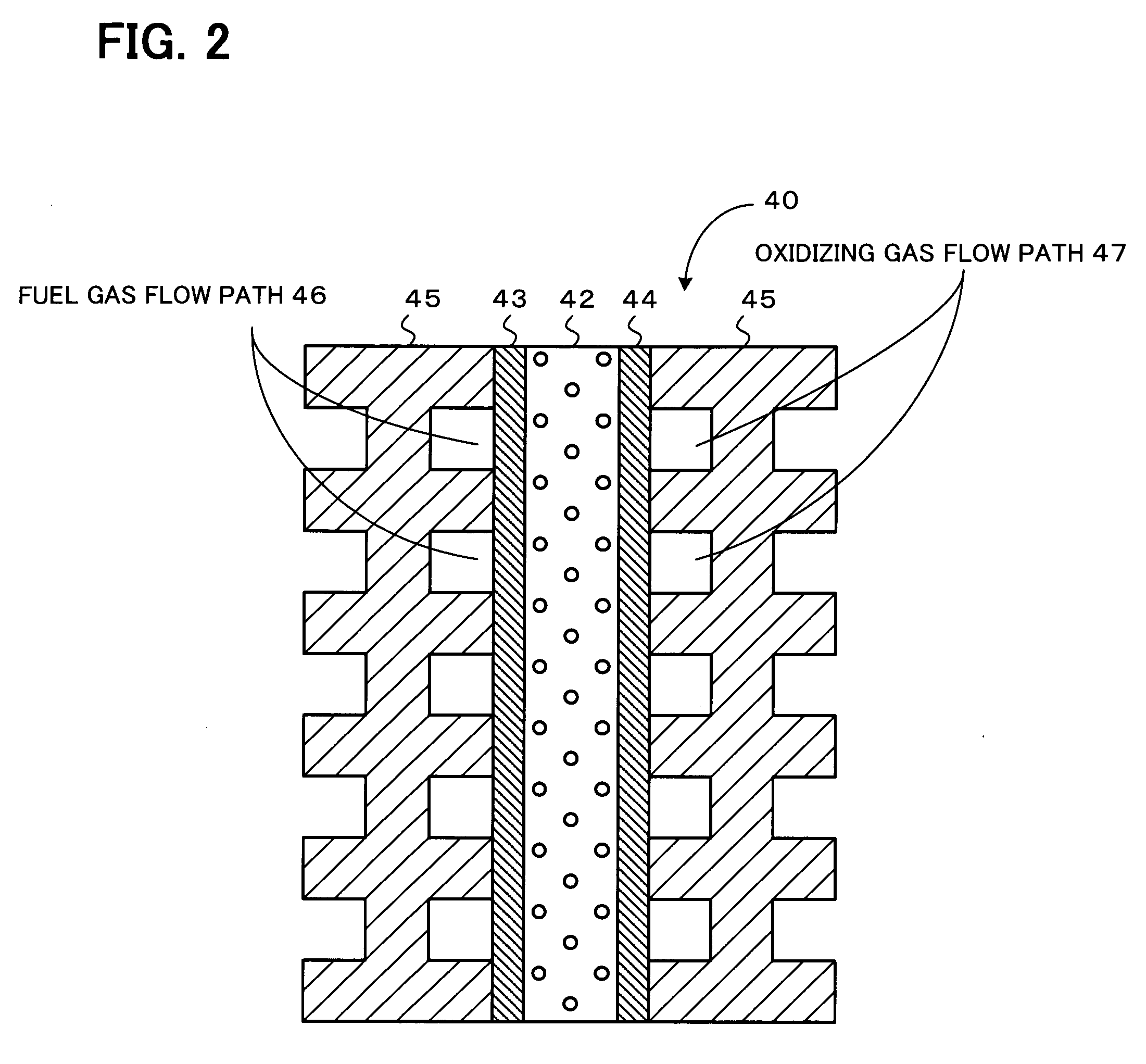
[0046]The fuel cell vehicle 10 includes a fuel cell stack 30 obtained by lamination of multiple fuel cells 40 that generate electric power through electrochemical reaction of hydrogen as a fuel gas and oxygen included in the air as an oxidizing gas. The fuel cell vehicle 10 also includes a motor 52 that is connected to the fuel cell stack 30 via an inverter 54, a battery 58 that is connected via a DC-DC converter 56 to power lines 53 for connecting the fuel cell stack 30 with the inverter 54, and an electronic control unit 70 that controls the operations of the whole fuel cell vehicle 10. A driveshaft 64 is linked to drive wheels 63,63 via a differential gear 62, so that power generated by the motor 52 is transmitted through the driveshaft 64 and is eventua...


PUM


Abstract

In a fuel cell vehicle according to one aspect of the invention, an amount of battery assist for a fuel cell stack is adequately set according to the setting of a mode position and an accelerator opening change rate. The driver's requirement for abrupt acceleration is inferred from a large value of the accelerator opening change rate. In this case, the amount of battery assist is increased to give a sufficient acceleration feeling to the driver. The driver's requirement for moderate acceleration is inferred, on the other hand, from a small value of the accelerator opening change rate. In this case, the amount of battery assist is reduced to restrict the acceleration and improve the fuel consumption. The setting of the mode position to a sports mode suggests the driver's preference to the acceleration over the fuel consumption. The amount of battery assist is thus increased to ensure the sufficient acceleration feeling. The setting of the mode position to an economic mode, on the other hand, suggests the driver's preference to the fuel consumption over the acceleration. The amount of battery assist is thus reduced to improve the fuel consumption.

Description

TECHNICAL FIELD[0001]The present invention relates to a fuel cell vehicle and more specifically pertains to a vehicle equipped with fuel cells that generate electrical energy through an electrochemical reaction of a fuel gas and an oxidizing gas.BACKGROUND ART[0002]Fuel cell vehicles are generally equipped with fuel cells that generate electrical energy through an electrochemical reaction of a fuel gas and an oxidizing gas. One proposed structure of the fuel cell vehicle is equipped with a battery as well as the fuel cells and controls a power demand required for the fuel cells during acceleration according to the state of charge of the battery. For example, a control technique proposed in Patent Document 1 does not set a significantly large value to the power demand for the fuel cells at a certain variation of the driver's depression amount of an accelerator pedal, when the battery has a sufficiently high state of charge and ensures sufficient power assist even in the case of a lar...

Claims


Application Information

Patent Timeline
IPC IPC(8): B60L11/18G06F17/00
CPCB60L11/1851Y02E60/50B60L11/1887B60L15/2045B60W10/08B60W10/26B60W10/28B60W20/00B60W30/182B60W2540/106H01M8/0494H01M8/04947H01M16/006H01M2250/20Y02T10/705Y02T10/7283Y02T90/32Y02T90/34B60L11/1881Y02T10/72B60L15/2072B60L2240/12B60L2240/423B60L2240/80B60L2250/28B60L1/003B60L15/20B60L2240/421B60L2240/461B60L2250/24B60L2250/26B60L50/51B60L58/12B60L58/30B60L50/72B60L58/40Y02T10/64Y02T10/70Y02T90/40Y02E60/10B60W20/19H01M8/00B60W2510/0283
Inventor SHIGE, MASAHIRO
Owner TOYOTA JIDOSHA KK
Why Eureka
Try Eureka