Gearshift Device

a gear shift and gear technology, applied in the direction of mechanical control devices, process and machine control, instruments, etc., can solve the problems of unintentional rotation of gearshift knobs, so as to prevent unintentional gear shift operations

Inactive Publication Date: 2009-04-30
KK TOKAI RIKA DENKI SEISAKUSHO
View PDF17 Cites 47 Cited by
  • Summary
  • Abstract
  • Description
  • Claims
  • Application Information

AI Technical Summary

Benefits of technology

[0008]Accordingly, it is an object of the present invention to provide a gearshift device ensuring the prevention of unintentional gearshift operations.

Problems solved by technology

More specifically, when using a gearshift lever, a gearshift gate would be necessary to guide the lever in a predetermined direction, whereas such guiding means is unnecessary when using the rotary gearshift knob.
However, for example, when the brake pedal is inadvertently depressed, the gearshift knob may be unintentionally rotated.
The gearshift knob may also be rotated in such an unintentional manner when the rotation of the gearshift knob cannot be restricted for one reason or the other such as failure of the solenoid.
Therefore, in the gearshift device of the above publication, there still remains the possibility of erroneous operation of the gearshift knob.

Method used


Image

  • Gearshift Device
  • Gearshift Device
  • Gearshift Device

Examples


first embodiment

Advantages of First Embodiment

[0136]The gearshift device 11 of the first embodiment has the advantages described below.

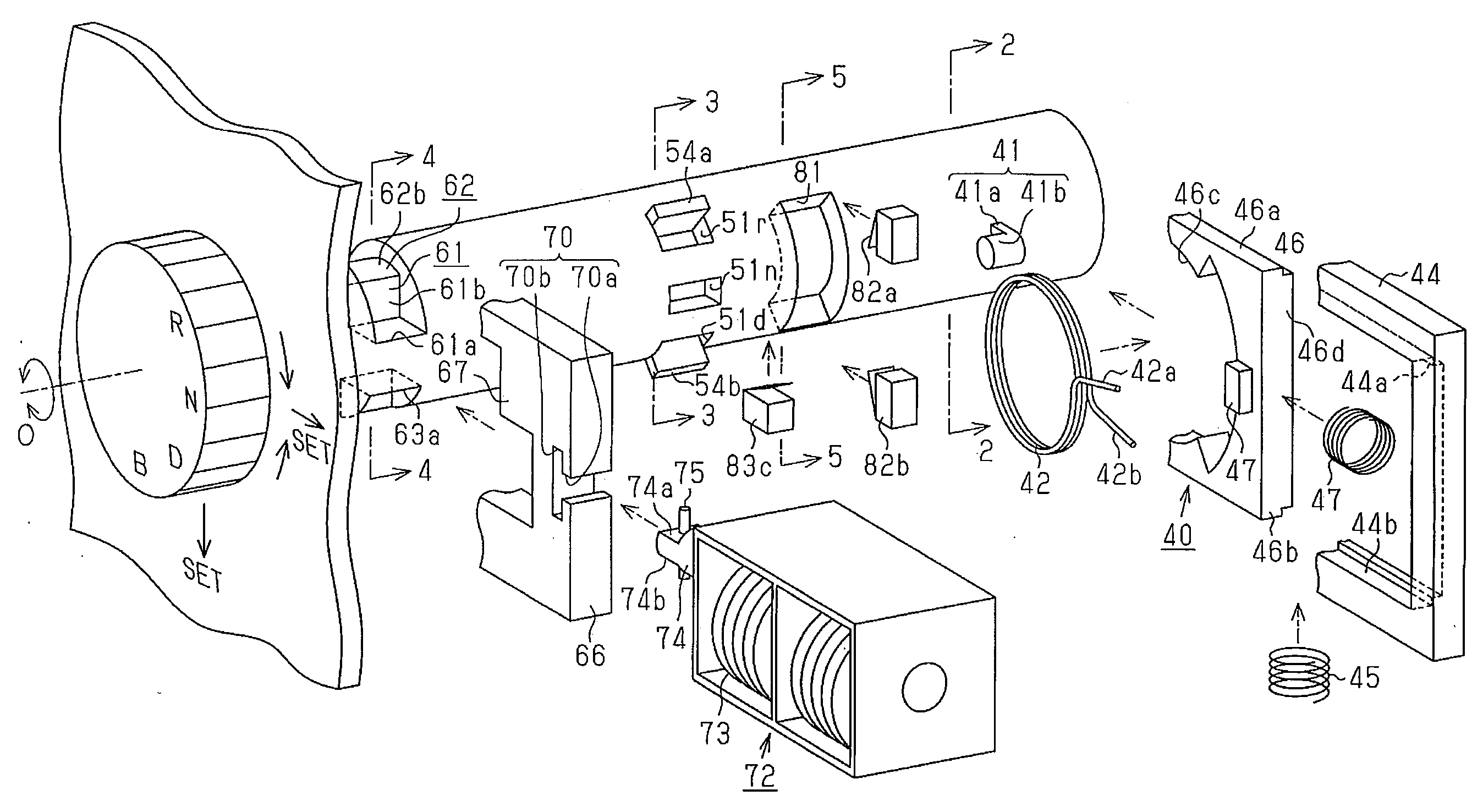
[0137](1) Three fitting recesses 51r, 51n, and 51d each corresponding to the three rotation positions (R, N, D) of the knob 22 are formed on the outer surface of the shaft 31. The first fitting projection 52a fittable to each fitting recess 51r, 51n, 51d is formed on the inner circumferential surface of the insertion hole 32 of the housing 21. When the knob 22 is rotated to one of the three rotation positions, the corresponding one of the fitting recesses 51r, 51n, and 51d faces the first fitting projection 52a. Thus, the sideward sliding of the knob 22 is permitted to determine the shifting to the gear position corresponding to one of the rotation positions only when the knob 22 is rotated to the one of the rotation position. That is, the operations in two different directions for the rotation and for the sideward sliding of the knob 22 are necessary when shifting ...

second embodiment

[0150]A gearshift device according to a second embodiment of the present invention will now be described. The second embodiment differs from the first embodiment in the structure of the rotation restriction means for restricting the rotation of the knob 22.

[0151]As shown in FIG. 14, a circular ring plate-shaped lock 101 is inserted into the shaft 31 in a slidable and rotatable manner in the lock accommodation portion 65 of the housing 21. A restriction cutout 102 extending in the circumferential direction of the lock 101 is formed at the portion on the arrow X side of the inner circumferential surface of the lock 101. The length of the restriction cutout 102 in the circumferential direction of the lock 101 corresponds to the rotation range of the shaft 31 determined based on the engagement relationship of the first and the second contact walls 54a, 54b and the first fitting projection 52a, described above, shown in FIG. 7. Furthermore, as shown in FIG. 14, when the rotation position...

third embodiment

[0162]A gearshift device of the third embodiment of the present invention will now be described. The third embodiment is basically formed in a manner similar to the gearshift device 11 shown in FIGS. 1 to 13. The third embodiment differs from the first embodiment in the structure of the recovery means for returning the knob 22 to the original position in the movement direction when the force in the movement direction of the knob 22 is eliminated. The third embodiment may be applied to the second embodiment.

[0163]As shown in FIG. 16(a), a spring accommodation hole 111 is formed at an inner end face of the shaft 31. The spring accommodation hole 111 accommodates a cylindrical slidable member 113 with a compression coil spring 112 in a manner preventing the slidable member 113 from falling out. The distal end of the slidable member 113 has a spherical shape and is projected out from the inner end face of the shaft 31. The slidable member 113 is arranged to be movable towards the inner ...


PUM


Abstract

A gearshift device for an automatic transmission that prevents inadvertent gearshift operations. The gearshift device includes a shaft-shaped gearshift member partially exposed from a housing so as to be rotatable relative to the housing about a rotation axis and movable sidewards in at least a first direction that intersects the rotation axis. The gearshift member is rotated to a plurality of rotation positions respectively corresponding to the gear positions of the automatic transmission. A movement restriction unit permits movement of the gearshift member in the first direction only when the gearshift member is rotated to a selected one of the rotation positions to determine shifting to the gear position corresponding to the selected one of the rotation positions. A control unit provides the automatic transmission with a gearshift control signal corresponding to the selected one of the rotation positions.

Description

CROSS-REFERENCE TO RELATED APPLICATIONS[0001]This application is based upon and claims the benefit of priority from the prior Japanese Patent Applications No. 2007-284055, filed on Oct. 31, 2007, and No. 2007-284056, filed on Oct. 31, 2007, the entire contents of which are incorporated herein by reference.BACKGROUND OF THE INVENTION[0002]The present invention relates to a gearshift device for switching a gear position of an automatic transmission.[0003]In the prior art, a so-called by-wire gearshift device which is a gearshift device mechanically separated from an automatic transmission in a vehicle is widely used. The gearshift device detects the position of a gearshift lever serving as a gearshift means operated by a user as an electric signal and electronically shifts the gear position (connection state) of the automatic transmission based on the detection signal. A mechanical structure such as link mechanism is thus unnecessary. This reduces limitations on the location of the ge...

Claims


Application Information

Patent Timeline
Patent Type & Authority Applications(United States)
IPC IPC(8): G05G1/08
CPCB60K37/06B60K2350/102F16H59/08Y10T74/2014F16H2059/081Y10T74/20474Y10T74/20085F16H61/22B60K2370/126
Inventor SEKI, YOSHIYUKI
Owner KK TOKAI RIKA DENKI SEISAKUSHO
Why Eureka
Try Eureka