Dual crankshaft engine with counter rotating inertial masses

Inactive Publication Date: 2009-04-30
FORD GLOBAL TECH LLC
View PDF18 Cites 36 Cited by
  • Summary
  • Abstract
  • Description
  • Claims
  • Application Information

AI Technical Summary

Benefits of technology

[0011]In operation, the cylinders preferably have a firing order where the piston motion is diametrically symmetrical. That is to say that the rear piston of the left cylinder bank has a motion that is substantially identical to and in phase with the motion of the front piston of the right cylinder bank. Likewise, the second piston from the rear of the left bank is in phase with the second piston from the front of the right bank, etc. Also, the to

Problems solved by technology

The vibration often creates a disturbance in a vehicle passenger compartment and is considered undesirable.
All conventional, single crankshaft, piston engines have a firing frequency vibration caused by uneven torque delivery to the flywheel.
The torque that causes vibrational speed variations of the flywheel reacts against the cylinder block and causes torsional vibration of the cylinder block.
This fluctuating torque causes one source of vibration.
Other disturbing engine vibrations are caused by unbalanced accelerations of internal engine components, especially linear accelerations of the piston masses within the cylinder bores.
Inline and opposed 6-cylinder engines, as well as inline and 90 deg

Method used


Image

  • Dual crankshaft engine with counter rotating inertial masses
  • Dual crankshaft engine with counter rotating inertial masses
  • Dual crankshaft engine with counter rotating inertial masses

Examples


Embodiment Construction

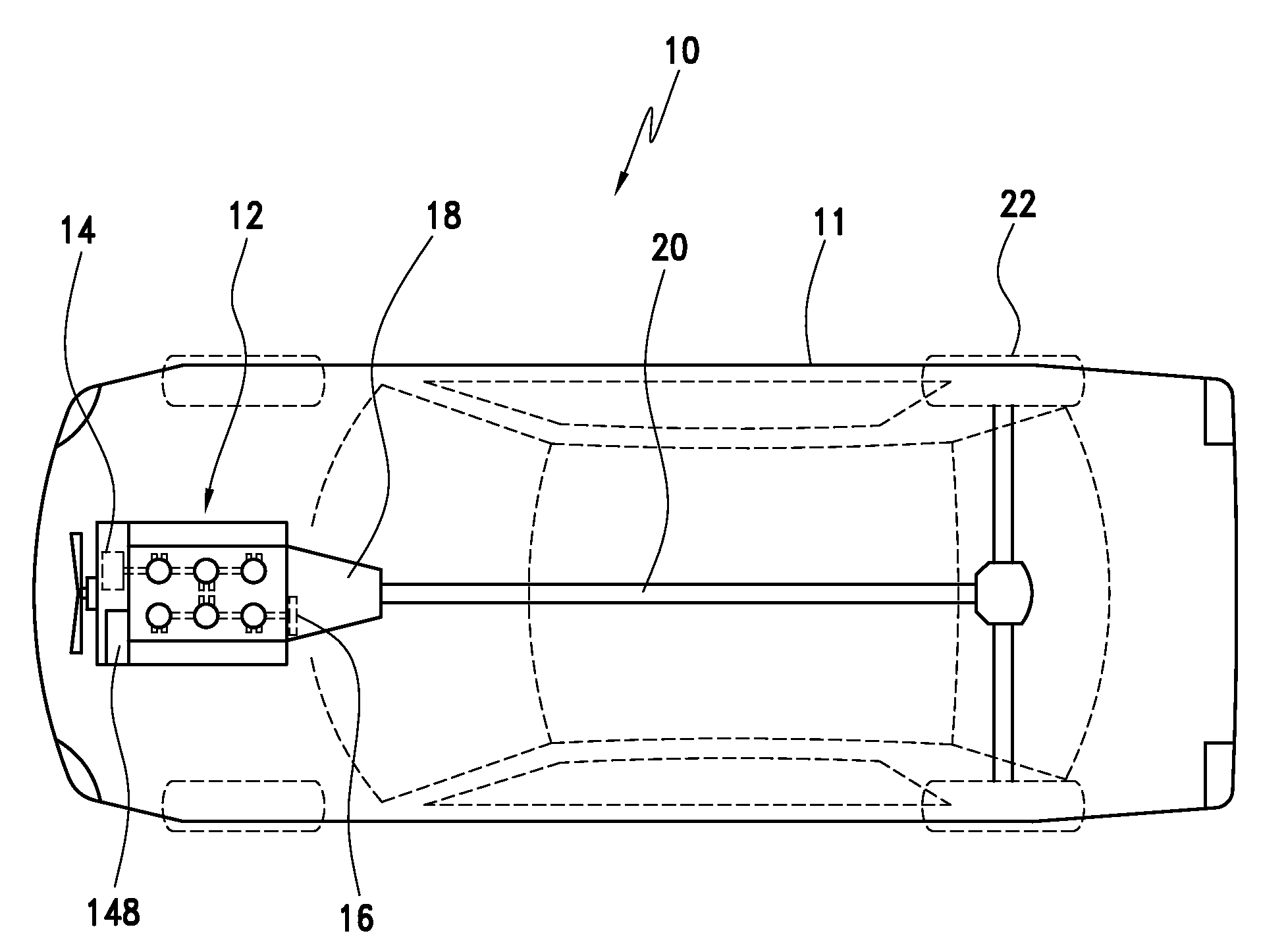
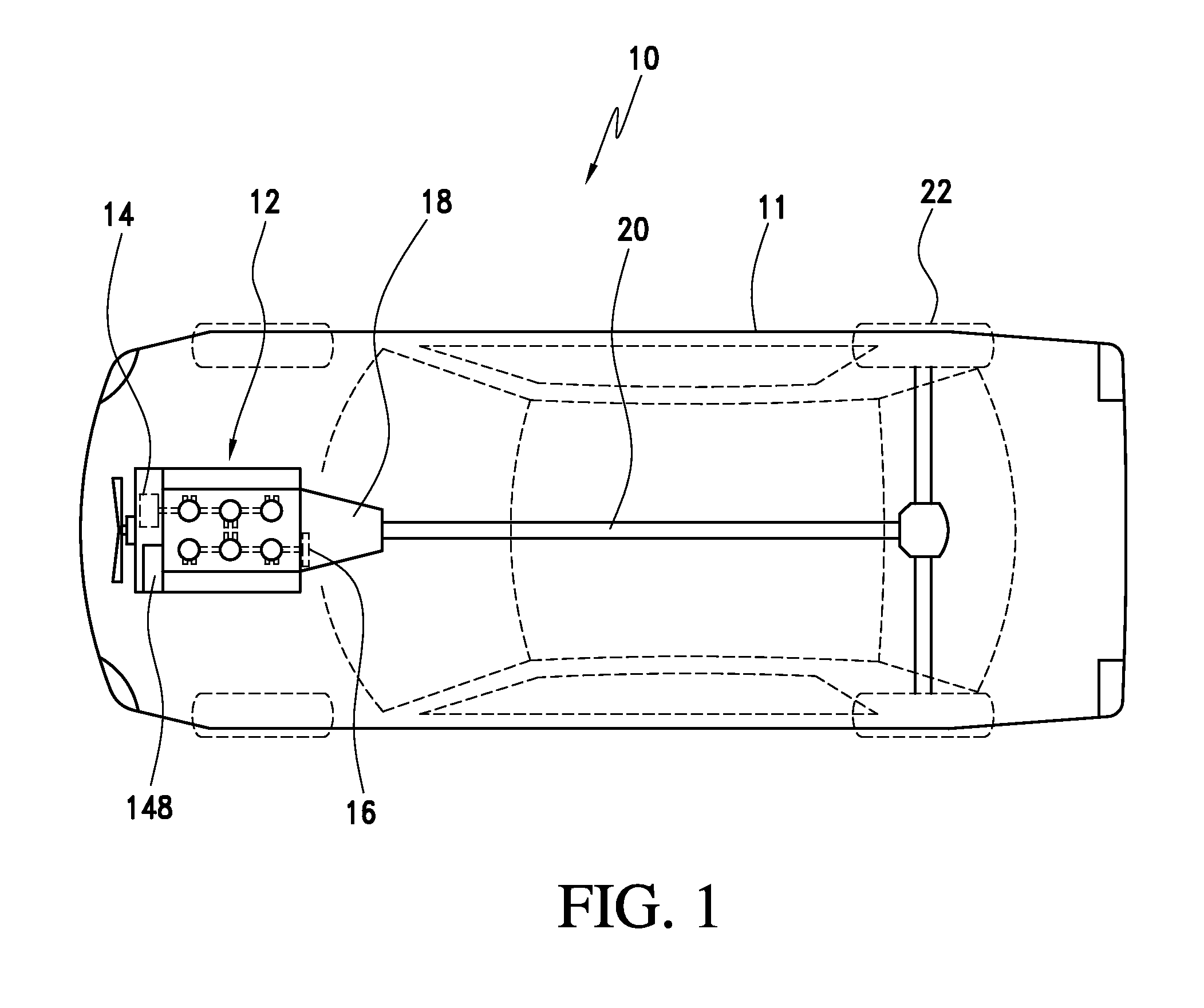
[0020]With initial reference to FIG. 1, there is shown an automotive vehicle 10 having a body 11 and a dual crankshaft engine 12. The engine 12 is preferably attached to a first mass 14, having an associated inertia such as motor / generator or a starter motor. The engine 12 is also attached to a second mass 16, having an associated inertia, such as torque converter or a flywheel. The rotational inertia of the first mass 14 is preferably the same as the rotational inertia of the second mass 16. Power from the engine 12 is transmitted through the flywheel or torque converter to a transmission 18, then to the other portions of a powertrain 20 and eventually drives wheels 22.

[0021]In FIG. 1, the vehicle 10 is shown as a rear wheel drive vehicle but, as will become readily apparent from the discussion below, any type of powertrain arrangement, including a front wheel or all wheel drive, could be used. At this point, it should be readily recognized that a flywheel would be commonly used as...


PUM


Abstract

A dual crankshaft internal combustion engine is symmetrically constructed to form a perfectly balanced engine assembly. A first crankshaft, having a first end, a second end, and being formed of a shape and with a torsional flexibility, is housed within a cylinder block and connected to a first series of cooperating pistons and cylinders. A second crankshaft, having a first end and a second end, is formed of substantially the same shape as the first crankshaft and has substantially the same torsional flexibility as the first crankshaft. The second crankshaft is also housed within the cylinder block and connected to a second series of cooperating pistons and cylinders, while being positioned parallel to the first crankshaft, with the first end of the first crankshaft being positioned adjacent to the second end of the second crankshaft.

Description

FIELD OF INVENTION[0001]The present invention pertains to the art of internal combustion engines used in vehicles and, more specifically, to a balance and noise reduction system for a dual crankshaft engine.BACKGROUND OF THE INVENTION[0002]Conventional internal combustion engines employ piston and cylinder arrangements that tend to vibrate during operation. The vibration often creates a disturbance in a vehicle passenger compartment and is considered undesirable.[0003]Most internal combustion engines develop power in impulses generated by the explosion of a combination of air and fuel in the engine's cylinders. The power is transferred to pistons that are located in the cylinders and are coupled to a rotating crankshaft with connecting rods. The power then flows to a flywheel that is connected to other downstream components of a powertrain. All conventional, single crankshaft, piston engines have a firing frequency vibration caused by uneven torque delivery to the flywheel. On a com...

Claims


Application Information

Patent Timeline
IPC IPC(8): B60K6/22B60K6/30F02B75/06F02B75/18
CPCB60K5/08B60K6/24B60K6/26Y02T10/6295F02B75/225Y02T10/6226B60K6/485Y02T10/62
Inventor BERGER, AL HENRYCLARKE, JAMES R.
Owner FORD GLOBAL TECH LLC
Why Eureka
Try Eureka