Bicycle rack

a bicycle rack and bicycle technology, applied in the field of bicycle racks, can solve the problems of poor durability, poor appearance of many known bicycle racks, poor density of bicycles being stored, etc., and achieve the effects of convenient engagement, good access, and dense bicycle storag

Inactive Publication Date: 2009-04-30
PORTERCORP
View PDF21 Cites 8 Cited by
  • Summary
  • Abstract
  • Description
  • Claims
  • Application Information

AI Technical Summary

Benefits of technology

[0004]In one aspect of the present invention, a bicycle rack includes a post and a plurality of loops attached at top and bottom locations to the post and defines a space with an adjacent one of the loops for receiving a bicycle wheel. Each loop defines a plane and extends radially from the post for at least about 90 degrees around the post. By this arrangement, an optimal dense storage of bicycles is provided, while still providing easy engagement of the bicycle with the rack, and while also allowing good access for locking and unlocking the bicycle from the rack.

Problems solved by technology

However, many known bicycle racks suffer from a poor appearance, poor density of bicycles being stored, poor durability and high cost.
Also, as the storage density of a rack is increased, the ability to lock or unlock one's bicycle decreases due to the interference of adjacent bicycles.
It is noted that bicycles are often stolen when the front (or rear) tire / rim is locked to a bicycle rack, with the thief taking everything except the front (or rear) tire / rim, since the missing tire / rim can be easily replaced.
An additional problem is that densely stored bicycles tend to rub against, fall over on, and / or hang up on each other during placement and removal of the bicycle, resulting in damage to both of the adjacent bicycles.

Method used


Image

  • Bicycle rack
  • Bicycle rack
  • Bicycle rack

Examples


Embodiment Construction

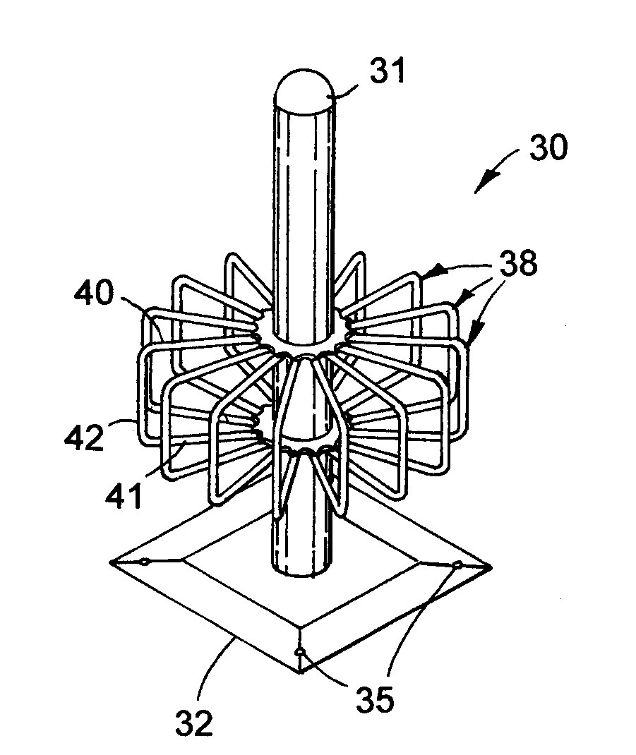
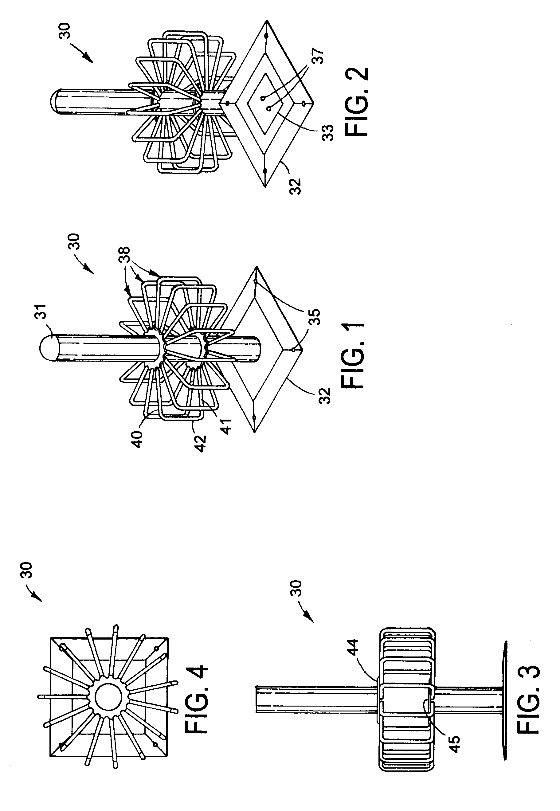
[0020]A bicycle rack 30 (FIGS. 1-2) includes a post 31 (also called a “support”) anchored to the ground using a ground-anchored base plate 32 and a post-anchoring flange plate 33, the base plate 32 being secured to the ground 34 using corner anchor bolts 35, and the flange plate 33 securing the post 31 to the base plate 32 using bolts 37. It is noted that the post 31 can be anchored to the ground in a number of different ways, such as by fasteners and plates as illustrated, or by welding to existing building structure, by attaching to existing foundation structure, or by placing the post in a foundation / concrete.

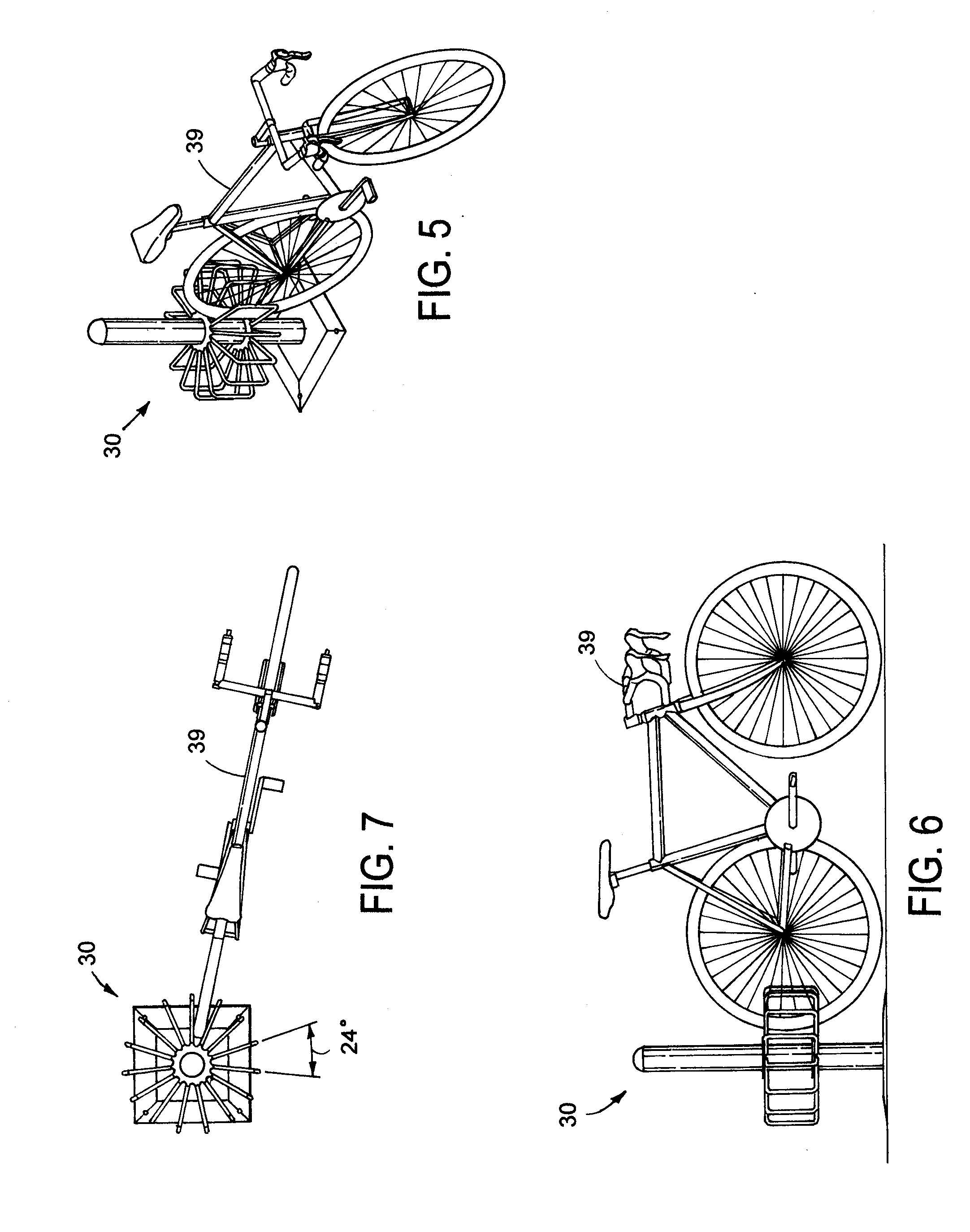
[0021]A plurality of “square” loops 38 (also called “structural members”) are attached to sides of the post 31, each loop 38 defining a vertical plane and extending radially preferably at about 20-30 degree circumferential spacing (or more preferably at about 24 degree circumferential spacing. Each loop 38 is U-shaped, and includes a horizontal linear top leg 40 (or “segment...


PUM


Abstract

A bicycle rack includes a plurality of loops attached to the post, each loop being attached at top and bottom locations to a support and defining a space with an adjacent one of the loops for receiving a bicycle wheel. Each loop extends radially from the support at about 24 degrees angular spacing, with each loop's top located about 18 inches above the ground, and a bottom about 10 inches from the ground. Each loop includes horizontal linear top and bottom segments and a horizontal linear bottom segment, which combines with the angular spacing and vertical dimensions to provide easy reach for a bicycle rider locking/unlocking their bicycle from the rack. The support for the loops can be a post, a wall or the like.

Description

[0001]This application claims benefit under 35 U.S.C. § 119(e) of provisional application Ser. No. 60 / 982,583, filed Oct. 25, 2007, entitled BICYCLE RACK, the entire contents of which are incorporated herein by reference.BACKGROUND[0002]The present invention relates to bicycle racks, and more particularly to a bicycle rack for dense temporary storage of bicycles, including an ability to easily lock individual bicycles in place.[0003]Bicycle racks are often used to support bicycles in a stored standing position, such as at parks, meeting locations, work, and other destinations where people ride bicycles. However, many known bicycle racks suffer from a poor appearance, poor density of bicycles being stored, poor durability and high cost. Also, as the storage density of a rack is increased, the ability to lock or unlock one's bicycle decreases due to the interference of adjacent bicycles. It is noted that bicycles are often stolen when the front (or rear) tire / rim is locked to a bicycl...

Claims


Application Information

Patent Timeline
Patent Type & Authority Applications(United States)
IPC IPC(8): B62H3/00
CPCB62H3/04
Inventor PORTER, WILLIAM H.KREPLE, CHRISTOPHER J.
Owner PORTERCORP
Why Eureka
Try Eureka