Bidirectional power converters

a power converter and bidirectional technology, applied in the direction of dc network circuit arrangement, ac-dc conversion, efficient power electronics conversion, etc., can solve the problems of inability to provide the power required to the usb link in the pda or other mobile device does not have the capability to operate in the host mode and drive the usb link, and the device cannot power the usb link, so as to reduce the size and complexity of the converter

Inactive Publication Date: 2009-04-30
ANALOG DEVICES INT UNLTD
View PDF8 Cites 97 Cited by
  • Summary
  • Abstract
  • Description
  • Claims
  • Application Information

AI Technical Summary

Benefits of technology

[0010]Circuits and methods for bidirectional power conversion are provided that allow mobile and other devices to generate power suitable to support multiple modes of operation. The bidirectional power converters of the present invention may operate in both step up and step down configurations rather than having a single dedicated conversion function and use many of the same components thereby reducing converter size and complexity.

Problems solved by technology

In many instances, however, the USB link in the PDA or other mobile device does not have the capability to operate in the host mode and drive the USB link.
Although the mobile device may have the necessary controller circuitry to supervise USB communications, it does not have the capability to provide the power required to drive the USB link.
This is often due to the relatively low voltage provided by its battery and the inability of the mobile device to convert that voltage to level suitable to drive the USB link.
As a result, if the mobile device is connected to a device which may only operate as a USB slave, such as a memory stick, the mobile device cannot power the USB link, preventing the devices from communicating with one another.

Method used


Image

  • Bidirectional power converters
  • Bidirectional power converters
  • Bidirectional power converters

Examples


Embodiment Construction

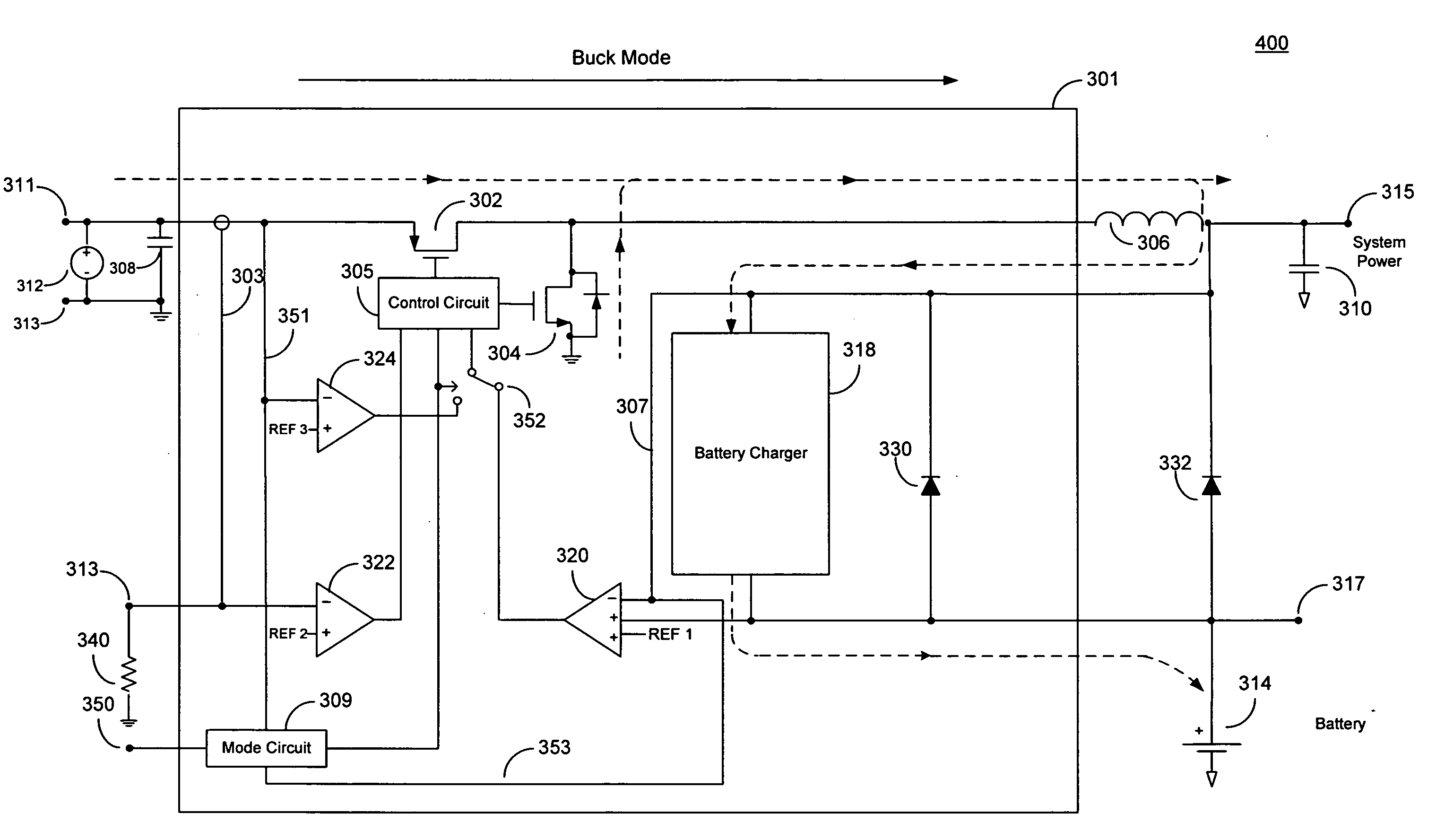
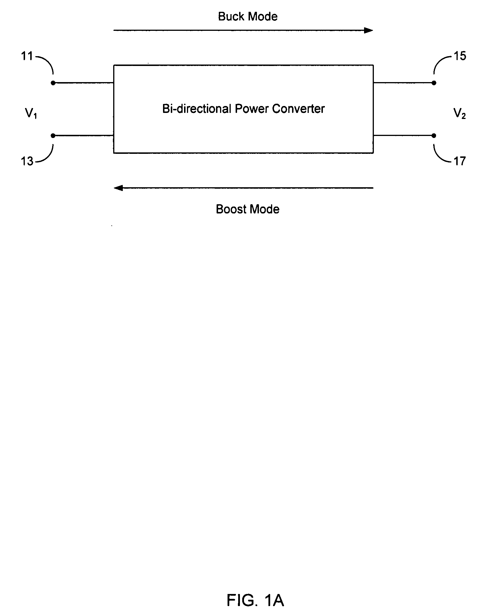
[0020]A general block diagram of one embodiment of a bidirectional power converter constructed in accordance with the principles of present invention is shown in FIG. 1A. As shown, system 10 includes a bidirectional power converter which may operate in at least two modes. Such modes may include a buck mode (i.e., step down) and boost mode (i.e., step up). Converter 10 may switch from one mode of operation to another depending on where an input signal is applied. For example, converter 10 may operate as a buck converter when a voltage V1 is applied across terminals 11 and 13 (in the direction indicated by the top arrow). In this case, converter 10 steps down voltage V1 and produces a reduced output voltage V2 at terminals 15 and 17. Conversely, converter 10 may operate as a boost converter when a voltage V2 is applied across terminals 15 and 17 (in the reverse direction indicated by the bottom arrow). In this case, the voltage is stepped up by converter 10 which produces and an outpu...


PUM


Abstract

Circuits and methods for bidirectional power conversion are provided that allow mobile and other devices to generate power suitable to support multiple modes of operation. The bidirectional power converters of the present invention may operate in both step up and step down configurations rather than having a single dedicated conversion function and use many of the same components thereby reducing converter size and complexity.

Description

BACKGROUND OF THE INVENTION[0001]The invention relates to bidirectional power converters. More particularly, the inventions described herein relate to systems and methods for creating bidirectional power converters that may be used to covert power in two different directions.[0002]Power conversion circuitry may be found in virtually every device that requires electricity. The purpose of power conversion circuitry is to transfer electrical power from a power source to a load, typically through certain conditioning and regulation circuitry. A typical application of power conversion circuitry is to convert AC power, provided by a power utility, to a regulated DC voltage suitable for use with consumer electronics. Although power conversion circuits are frequently implemented as stand alone systems, often they are constructed as integrated circuits (ICs) and used in various applications such as communications and computing systems.[0003]One type of commonly used power converter is a DC t...

Claims


Application Information

Patent Timeline
Patent Type & Authority Applications(United States)
IPC IPC(8): H02J1/00
CPCH02M3/1582Y02B70/1466H02M3/1588Y02B70/10H02M7/48H02M7/483
Inventor WALTER, WILLIAMDAS, SAUPAMA
Owner ANALOG DEVICES INT UNLTD
Why Eureka
Try Eureka