Methods and apparatus for interactive movable computer mediated information display

a technology of interactive movable computers and information displays, applied in static indicating devices, instruments, inductances, etc., can solve the problems of system loss, system loss, and wear of moving steel tape, so as to improve reliability, effectiveness, safety and affordability of the system

Inactive Publication Date: 2009-04-30
MURPHY TERENCE J +1
View PDF8 Cites 29 Cited by
  • Summary
  • Abstract
  • Description
  • Claims
  • Application Information

AI Technical Summary

Benefits of technology

[0052]As a user slides the movable display module along the rails, a computer program interprets the sensor data from the motion and presents the appropriate programmatic content on the display module. Other sensors may contribute to the computer input; and other displays or external effects may be controlled by the computer program as well. The movable display module comprises an enclosure, a touch screen and monitor, CPU, absolute encoder and encoder interface, audio amplifier and speakers, a radio frequency wireless network connection (Wifi) mounted on non-conductive material, and other sensors such as, but not limited to, cameras, smart card readers, and load cells. As a result of the rail system and the inclusion of the wireless data network connection, no cabling is required to travel with the movable display module. The absolute encoder means calibration is not lost on powering down; no daily reset is required. The system as a whole is engineered as an integrated unit, for ease of production and ease of installation. This all has the effect of substantially improving reliability, effectiveness, safety and affordability of the system compared to prior art.

Problems solved by technology

This system loses its place when power is lost or turned off, and must be recalibrated upon power restoration.
The moving steel tape is also subject to wear over time, causing failures.
A moving cable system is less robust than a system without moving cables, as continual flexing over time will degrade cables and cause eventual failure.
This results in increased maintenance costs and downtime for the device.
Position determination was based on a series of switches rather than an encoder, with a resultant lack of resolution.
This exhibit also used flexible power and data cabling and a cable management system, with resultant maintenance problems.
Problems with this system include:
This meant that the cables had to be run to a moving device over a fairly long run, which often led to cable failure due to repeated bending.
Large, heavy mass and support framework: the Reading Wall used large plasma monitors, which were heavy for users to drag along the track and which required heavy-duty support systems.
The plasma monitors and the required supports were large and expensive.
Expensive and non-robust braking: Large and heavy displays in motion need a way to stop them at end of travel.
Particle brakes are costly, have high drag when not engaged (and therefore make the system harder to use), and are a repeated source of failure in respect to the gear engagement to the track.
Lack of ease of installation: the Reading Wall system as a whole required several days to install, including cable runs through the ceiling and bolting heavy frameworks to supports, often in both floor and ceiling.
However the Interactive Wall had all the problems noted above, with one exception.
In fact, the Interactive Wall added another, different failure point by adding the onboard computer, as that configuration used standard hard drives which may fail when continually exposed to motion, especially if the brakes fail causing the hard drives to be subject to hard shocks.
Both the Reading Wall and the Interactive Wall used plasma monitors, which had a high failure rate due to stress on the monitor itself from motion and sudden stops and shocks.
This added considerably to maintenance costs.
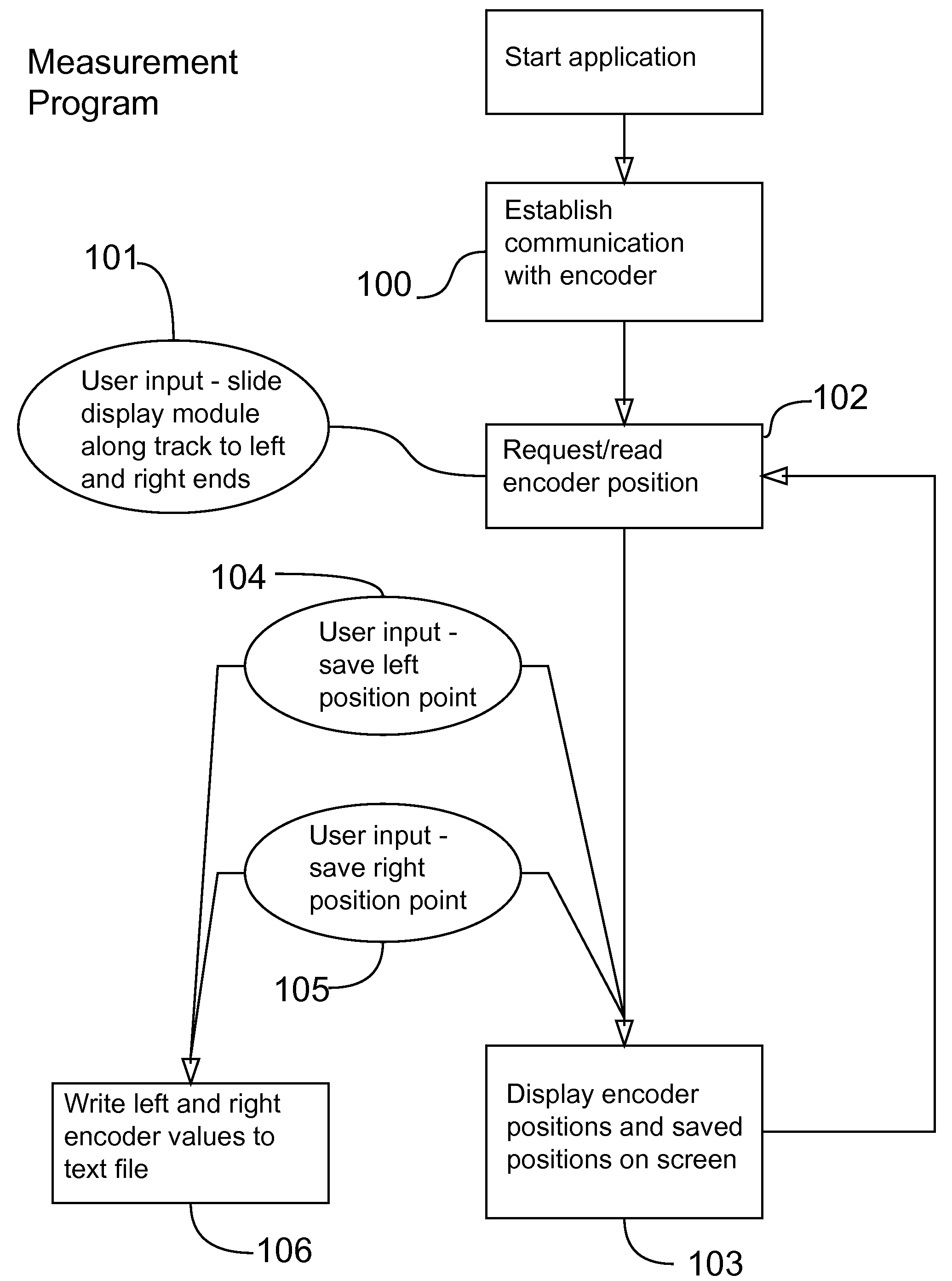
However this system still uses incremental encoding and places the computer processor external to the display module.
It also still uses cabling and cable guides for power and data delivery, with the attendant propensity for failure.
However, the Neutrino is very expensive, is not designed for easy replication, and like other X-Y moving monitor exhibits built since, has a lot of down time and high maintenance requirements.
The expense and high maintenance costs put this and similar systems financially out of reach for many uses, like smaller museums or educational centers.
Since both of this system's encoders are incremental encoders, not absolute, they require a complex, manual resetting procedure in the case of power loss (made even more complex by the fact that there are two different types of encoder).
Where the power exits the vertical rods and runs to the monitor itself is also a cable run; as noted above, cable and cable management systems are prone to failure in high-use situations.
Counterweight systems, cables and cable management systems, and hanging control rods do not survive well in environments where a million uses a year is likely; for example, one ten-year-old hanging full-weight off the monitor can cause severe stress to the system.
Since the interaction for X-Y systems like this one depends on the very motion that tends to cause breakdown, these systems are inherently prone to failure.
Further problems with all the movable monitor systems noted above include:
Lack of ease of production: All of the above systems were produced as site-specific, custom instances, which added to their cost.
They were not designed to be produced in large numbers, since they were too expensive to appeal to a large market.
Lack of ease of assembly and installation: They are time-consuming to assemble and require experts to perform the assembly and installation.
Requiring daily calibration: Incremental encoders require manual resetting every time they lose power, which is a liability in commercial or museum settings where technicians may not be available on a daily basis to restart a system.
Difficult to maintain: The number of subsystems in all these prior art systems that have failure-prone components (counterweight systems, hard drives, cables and cable management systems, particle brakes, plasma monitors) combine to create a system that has frequent, high-cost failures that must be repaired by experts.

Method used


Image

  • Methods and apparatus for interactive movable computer mediated information display
  • Methods and apparatus for interactive movable computer mediated information display
  • Methods and apparatus for interactive movable computer mediated information display

Examples


Embodiment Construction

[0112]The invention is illustrated by way of example and not by way of limitation in the figures of the accompanying drawings in which like references indicate similar elements. References to embodiments in this disclosure are not necessarily to the same embodiment, and such references mean at least one. While specific implementations are discussed, it is understood that this is done for illustrative purposes only. A person skilled in the relevant art will recognize that other components and configurations may be used without departing from the scope and spirit of the invention.

[0113]In the following description, numerous specific details are set forth to provide a thorough description of the invention. However, it will be apparent to those skilled in the art that the invention may be practiced without these specific details. In other instances, well-known features have not been described in detail so as not to obscure the invention.

[0114]Although a diagram may depict components as ...


PUM


Abstract

In embodiments, methods and systems are presented for physical interaction with computer-mediated information. A movable display module (including a touch screen monitor, CPU, absolute encoder and other sensors, and wireless network connection) is mounted on and can be moved along rails. The rails serve four purposes relating to the movable display module:1) to provide DC power and / or data through the rails to the equipment;2) to act as a rack gear for absolute encoding of physical position;3) to provide physical support;4) to act as guide tracks.As the display module slides along the rails, a computer program receives positional and other sensor data. The program maps the sensor data to programmatic content, and presents said content on the display module or on other displays or in external effects such as lights or robotics. The entire system is designed for reliability, affordability, and ease of mass production.

Description

CROSS-REFERENCE TO RELATED APPLICATIONS[0001]Not applicable.FEDERALLY SPONSORED RESEARCH[0002]Not applicable.[0003]The following is the logical description and flow of the software programs required to run a first embodiment of the current invention. This information appears in flowchart form in FIGS. 8, 9, and 10. The software contains several programs for different tasks, as noted. In other embodiments, similar routines may control other aspects of the embodiments.[0004]Measurement Program: The Measurement Program is a software program used to measure the range of motion the movable display module will travel, and mark its endpoints. In order to calibrate the software so that it is aware of its position on the track, the measurement software must be run so that the left endpoint and right endpoint numeric encoder positions of the track can be determined. Once the left and right endpoint positions have been recorded, the software will know the physical position of the movable displ...

Claims


Application Information

Patent Timeline
Patent Type & Authority Applications(United States)
IPC IPC(8): G09G3/00H02J17/00
CPCG06F1/1601
Inventor MURPHY, TERENCE J.BROWNING, MATTHEW C.
Owner MURPHY TERENCE J
Why Eureka
Try Eureka